The Gordon Bennett Air Race 1911 Part 1: Nieuport IV

3 years 3 months ago #421
by Stevef
The Gordon Bennett Air Race 1911 Part 1: Nieuport IV was created by Stevef
Evening All,
In 1911 the third Gordon Bennett air race was held at the Royal Aeronautical Society flying field at Eastchurch on the Isle of Sheppey, Kent. This was the same place that in 1910 Moore-Brabazon had flown the first mile in Britain in an all British machine - the Short No 2 biplane, which was the subject of an earlier build. There were 6 competitors in the air race, 3 French, 2 British and one American. Four aircraft types were flown, the Nieuport ii, Nieuport iv, Bleriot XXIII and a Wright Type R. Eastchurch is an important site in the history of aviation for a number of reasons which I have described in the build of the Short No 2 biplane, and I am continuing with an Eastchurch theme by building models of the 6 aircraft which took part in the 1911 air race. All of them will be scratch builds in God's Own Scale: I have found drawings of the Nieuport types but am still searching for drawings of the Bleriot. The Wright Type R was a Type B which had a reduced wing span and other modifications: I am having to rely on photographs for the details of this particular type.
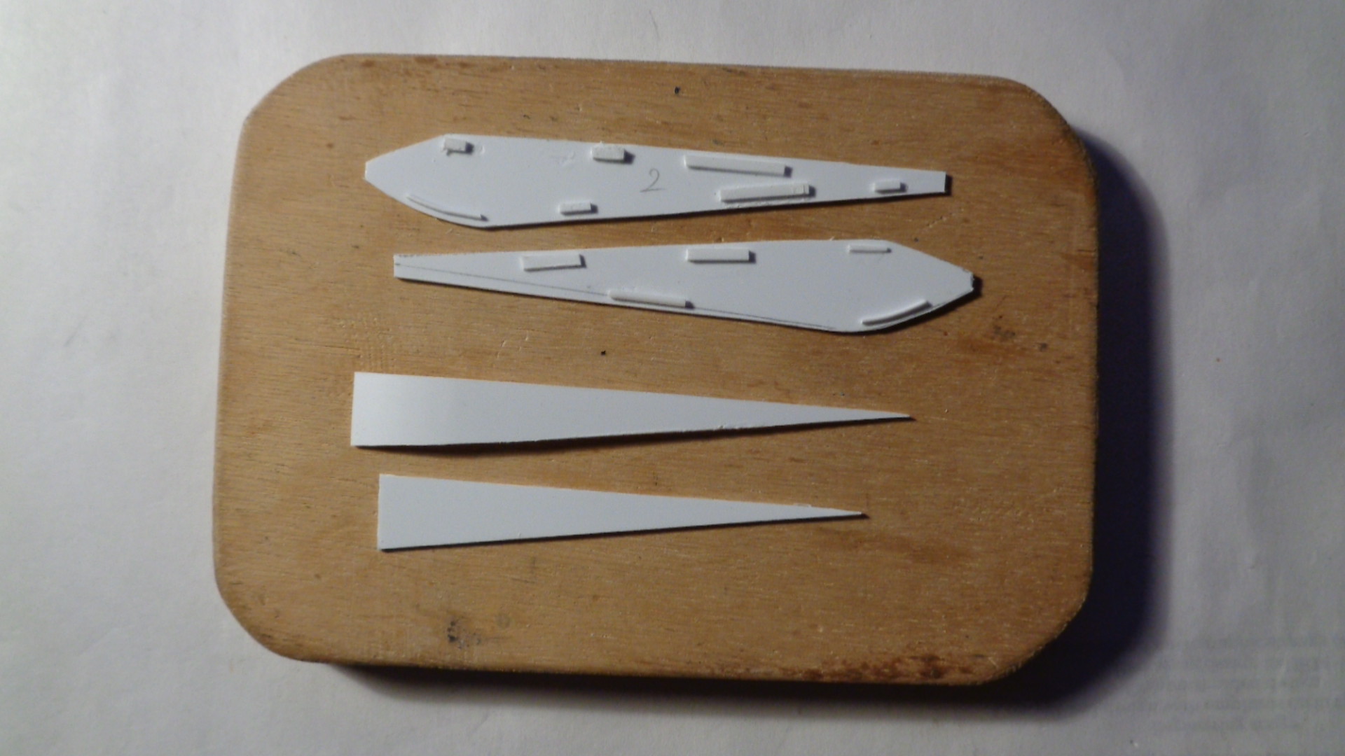
The Neuport iv was flown by C. Weymann who was the winner of the competition. I have drawings and a photo of Weymann standing by his machine taken while he was at Eastchurch, so this seemed to be a good subject to start with. I cut out the wing blanks, the horizontal tail surfaces and rudder. 10 x 20 thou Evergreen strip was glued to these surfaces to represent the ribbing:


(NB the Nieuport IV was a monoplane - I am making tow models of this type at the same time). I applied Mr Surfacer 1000 to the ribs and sanded these down to get a series of very slight ridges to represent the ribs:

The fuselage sides, top and bottom were cut from 30 thou card and scrap plastic cemented to the edges to help keep the joints square and provide a surface for adhesion:
I made a floor, seat, and control wheel and added some ribs to the fuselage sides from thin plastic strip. The interior was painted in clear doped linen for the cockpit sides with wood for the ribs. Very little of the interior will be visible on the completed model and as I have no photographs of the interior either, I have kept things simple.

The fuselage sides and bottom were glued together but the top has been laid on for the moment because I still have to cut out the opening at the front:

I now need to make a mould for the cowling and upper front fuselage plate, so that I can make the cockpit cutout the correct size. The engine and propellor will follow.
Stevef.
In 1911 the third Gordon Bennett air race was held at the Royal Aeronautical Society flying field at Eastchurch on the Isle of Sheppey, Kent. This was the same place that in 1910 Moore-Brabazon had flown the first mile in Britain in an all British machine - the Short No 2 biplane, which was the subject of an earlier build. There were 6 competitors in the air race, 3 French, 2 British and one American. Four aircraft types were flown, the Nieuport ii, Nieuport iv, Bleriot XXIII and a Wright Type R. Eastchurch is an important site in the history of aviation for a number of reasons which I have described in the build of the Short No 2 biplane, and I am continuing with an Eastchurch theme by building models of the 6 aircraft which took part in the 1911 air race. All of them will be scratch builds in God's Own Scale: I have found drawings of the Nieuport types but am still searching for drawings of the Bleriot. The Wright Type R was a Type B which had a reduced wing span and other modifications: I am having to rely on photographs for the details of this particular type.
The Neuport iv was flown by C. Weymann who was the winner of the competition. I have drawings and a photo of Weymann standing by his machine taken while he was at Eastchurch, so this seemed to be a good subject to start with. I cut out the wing blanks, the horizontal tail surfaces and rudder. 10 x 20 thou Evergreen strip was glued to these surfaces to represent the ribbing:
(NB the Nieuport IV was a monoplane - I am making tow models of this type at the same time). I applied Mr Surfacer 1000 to the ribs and sanded these down to get a series of very slight ridges to represent the ribs:
The fuselage sides, top and bottom were cut from 30 thou card and scrap plastic cemented to the edges to help keep the joints square and provide a surface for adhesion:
I made a floor, seat, and control wheel and added some ribs to the fuselage sides from thin plastic strip. The interior was painted in clear doped linen for the cockpit sides with wood for the ribs. Very little of the interior will be visible on the completed model and as I have no photographs of the interior either, I have kept things simple.
The fuselage sides and bottom were glued together but the top has been laid on for the moment because I still have to cut out the opening at the front:
I now need to make a mould for the cowling and upper front fuselage plate, so that I can make the cockpit cutout the correct size. The engine and propellor will follow.
Stevef.
Please Log in to join the conversation.
3 years 2 months ago #422
by Stevef
Replied by Stevef on topic The Gordon Bennett Air Race 1911 Part 1: Nieuport IV
Evening All,
This should be a relatively simple and quick build, but I am making two models in tandem and as ever they are not quite the same and I have had the usual set-backs that any scratch build encounters from time to time. In this case it was moulding the curved upper section of the forward fuselage. I thought that the shape tapered from front to rear and made male and female moulds accordingly. However when I came to fit the first of the new parts to the fuselage I realised my error and had to carve new male and modify the female. Second time the shape was nearly right - the front of the cowling has parallel sides. The new parts were close enough to put on the model.

On the left is the male mould carved from basswood (lime), in the centre a moulded part and on the right the part cut from the plastic sheet and prepared ready to put into place.
I am making two variants of the Nieuport IV: one took part in the Gordon Bennett air race and had a rounded cockpit opening. The second was used by military services and had a different shaped cockpit opening. A firewall was added to the fronts of the fuselages from 30 thou card and a hole drilled to take the engine pin later. The Gordon Bennett aircraft was powered by a Gnome Omega Omega 14 cylinder 100hp rotary engine, the military aircraft had a 70 hp Gnome 7 cylinder rotary. Until I started this project I had not known of the 14 cylinder rotary: this was essentially two 7 cylinder engines with the crank cases bolted together with a common crank shaft. The torque of that engine must have been enormous! Both engines were constructed in the same way: I used a piece of round sprue of the right diameter and cut pieces to represent the crank case. The cylinders were pieces of 40 thou rod glued into place over a drawing of a 7 cylinder engine. In the case of the Omega Omega engine I put 7 cylinders in a row first, then turned the piece over and added the second row of cylinders so that they filled the gaps behind the first row.

After this photo was taken I added the push rods to the fronts of the cylinders from stretched sprue. I also added the cowlings to the fore parts of the upper fuselages and cleaned up the gaps with filler:

The above shows the racing aeropane and the double Omega engine - I have still to trim the push rods.
I put a small piece of rod next to the cowling to represent the petrol filler cap and then added the horizontal tail unit.

Holes need to be drilled for the undercarriage legs and tail struts and then I can cement the wings into place,
Thanks for looking.
Stevef.
This should be a relatively simple and quick build, but I am making two models in tandem and as ever they are not quite the same and I have had the usual set-backs that any scratch build encounters from time to time. In this case it was moulding the curved upper section of the forward fuselage. I thought that the shape tapered from front to rear and made male and female moulds accordingly. However when I came to fit the first of the new parts to the fuselage I realised my error and had to carve new male and modify the female. Second time the shape was nearly right - the front of the cowling has parallel sides. The new parts were close enough to put on the model.
On the left is the male mould carved from basswood (lime), in the centre a moulded part and on the right the part cut from the plastic sheet and prepared ready to put into place.
I am making two variants of the Nieuport IV: one took part in the Gordon Bennett air race and had a rounded cockpit opening. The second was used by military services and had a different shaped cockpit opening. A firewall was added to the fronts of the fuselages from 30 thou card and a hole drilled to take the engine pin later. The Gordon Bennett aircraft was powered by a Gnome Omega Omega 14 cylinder 100hp rotary engine, the military aircraft had a 70 hp Gnome 7 cylinder rotary. Until I started this project I had not known of the 14 cylinder rotary: this was essentially two 7 cylinder engines with the crank cases bolted together with a common crank shaft. The torque of that engine must have been enormous! Both engines were constructed in the same way: I used a piece of round sprue of the right diameter and cut pieces to represent the crank case. The cylinders were pieces of 40 thou rod glued into place over a drawing of a 7 cylinder engine. In the case of the Omega Omega engine I put 7 cylinders in a row first, then turned the piece over and added the second row of cylinders so that they filled the gaps behind the first row.
After this photo was taken I added the push rods to the fronts of the cylinders from stretched sprue. I also added the cowlings to the fore parts of the upper fuselages and cleaned up the gaps with filler:
The above shows the racing aeropane and the double Omega engine - I have still to trim the push rods.
I put a small piece of rod next to the cowling to represent the petrol filler cap and then added the horizontal tail unit.
Holes need to be drilled for the undercarriage legs and tail struts and then I can cement the wings into place,
Thanks for looking.
Stevef.
Please Log in to join the conversation.
3 years 2 months ago #423
by Stevef
Replied by Stevef on topic The Gordon Bennett Air Race 1911 Part 1: Nieuport IV
Evening All,
Making two models at the same time does slow things down a bit, especially when something does not work properly. I had to replace one of the pairs of wings after I had fixed them to the fuselage as they were so distorted that they looked horrible. So while I continued with one model I made a second set of wings for the other one. I have now finished one model and the second is a little further behind but should not take too long to get finished. I will post the build of the first model only here - photos of both will follow when I can photograph them in daylight.
The wings were glued to the fuselage - it is a butt joint but I have found that if the surfaces are smooth and clean a good strong joint can be achieved. I had to support the wing tips with one of my highly technical jigs while the cement was drying to ensure the correct anhedral was achieved:

Painting duly followed: the CDL was a mix of white with a small touch of Revell Okre (88) acrylics. I dilute the paint mix with water and apply as many coats as necessary to hide the filler and any other contrasts in the underlying surfaces - between 10 and 15 coats usually does it. The aluminium nose had an undercoat of gloss black followed by 2 or 3 thinned coats of Revell aluminium. Note that before I painted the nose I inseted the engine and small nose bracket that held the engine and propellor shaft steady:


The undercarriage consisted of two pairs of V struts, one at the front and one at the rear, with an inverted A strut in the middle. These were attached to a central bar which had paddle-like ends and a leaf spring axle in the centre. I decided to make the support struts from plastic strip and the central bar and axle from brass rod. The axle and bar were soldered together. The wheels were spoked without covers and were very small. I made the centres from 30 thou clear acetate sheet and scribed on the spokes. The tyres which were also narrow I made from rod wrapped around a thin paint brush handle immersed in near boiling water for about 10 seconds:

The struts were fixed to the underside of the fuselage and alignment checked by holding the central bar against them before the cement set. The struts were allowed to dry out thoroughly. The central strut which ran from the front fuselage to the rear of the undercarriage bar was a piece of plastic rod. All the undercarriage parts were painted as were the tyres:


The wheels were CA'd to the axle before the central bar was CA'd to the undercarriage legs. It is noteworthy that the wheels splayed outward at the bottom when the aircraft was on the ground so allowance had to be made for this. The pylon on the upper fuselage was made from rod. The number on the rudder of Weyman's machine was drawn by me based on a photograph taken at the meeting at Eastchurch. I made up two transfers and sized them before printing on my computer. After printing I varnished the transfers to seal the ink:

The model was rigged with rolled copper wire and the propellor fitted last. I will post photos of Weyman's machine as soon as I can - the second model will appear in a couple of days time when it too is finished.
Thanks for looking.
Making two models at the same time does slow things down a bit, especially when something does not work properly. I had to replace one of the pairs of wings after I had fixed them to the fuselage as they were so distorted that they looked horrible. So while I continued with one model I made a second set of wings for the other one. I have now finished one model and the second is a little further behind but should not take too long to get finished. I will post the build of the first model only here - photos of both will follow when I can photograph them in daylight.
The wings were glued to the fuselage - it is a butt joint but I have found that if the surfaces are smooth and clean a good strong joint can be achieved. I had to support the wing tips with one of my highly technical jigs while the cement was drying to ensure the correct anhedral was achieved:
Painting duly followed: the CDL was a mix of white with a small touch of Revell Okre (88) acrylics. I dilute the paint mix with water and apply as many coats as necessary to hide the filler and any other contrasts in the underlying surfaces - between 10 and 15 coats usually does it. The aluminium nose had an undercoat of gloss black followed by 2 or 3 thinned coats of Revell aluminium. Note that before I painted the nose I inseted the engine and small nose bracket that held the engine and propellor shaft steady:
The undercarriage consisted of two pairs of V struts, one at the front and one at the rear, with an inverted A strut in the middle. These were attached to a central bar which had paddle-like ends and a leaf spring axle in the centre. I decided to make the support struts from plastic strip and the central bar and axle from brass rod. The axle and bar were soldered together. The wheels were spoked without covers and were very small. I made the centres from 30 thou clear acetate sheet and scribed on the spokes. The tyres which were also narrow I made from rod wrapped around a thin paint brush handle immersed in near boiling water for about 10 seconds:
The struts were fixed to the underside of the fuselage and alignment checked by holding the central bar against them before the cement set. The struts were allowed to dry out thoroughly. The central strut which ran from the front fuselage to the rear of the undercarriage bar was a piece of plastic rod. All the undercarriage parts were painted as were the tyres:
The wheels were CA'd to the axle before the central bar was CA'd to the undercarriage legs. It is noteworthy that the wheels splayed outward at the bottom when the aircraft was on the ground so allowance had to be made for this. The pylon on the upper fuselage was made from rod. The number on the rudder of Weyman's machine was drawn by me based on a photograph taken at the meeting at Eastchurch. I made up two transfers and sized them before printing on my computer. After printing I varnished the transfers to seal the ink:
The model was rigged with rolled copper wire and the propellor fitted last. I will post photos of Weyman's machine as soon as I can - the second model will appear in a couple of days time when it too is finished.
Thanks for looking.
Please Log in to join the conversation.
3 years 1 month ago #425
by Stevef
Replied by Stevef on topic The Gordon Bennett Air Race 1911 Part 1: Nieuport IV
Evening All
I omitted to complete this thread with photos of the completed models....whoops!
To rectify this problem, here are photos of the models. First the Gordon Bennett racer as flown by C. Weymann who was the overall winner of the race:


Thanks for looking.
Stevef.
The second model is not of one of the racers of 1911 but of one of the first military aircraft to be used in Britain. It represents a machine operated by the 2nd Company of the Air Battallion of the Royal Engineers in 1911. It carried the serial B4 and later became 253 when the Air Battallion became 3 Squadron of the Royal Flying Corps on 13 April 1912. It was one of the first aircraft to be bought by the British government for military use.
a machine operated by the 2nd Company of the Air Battallion of the Royal Engineers in 1911. It carried the serial B4 and later became 253 when the Air Battallion became 3 Squadron of the Royal Flying Corps on 13 April 1912. It was one of the first aircraft to be bought by the British government for military use.


I omitted to complete this thread with photos of the completed models....whoops!
To rectify this problem, here are photos of the models. First the Gordon Bennett racer as flown by C. Weymann who was the overall winner of the race:
Thanks for looking.
Stevef.
The second model is not of one of the racers of 1911 but of one of the first military aircraft to be used in Britain. It represents a machine operated by the 2nd Company of the Air Battallion of the Royal Engineers in 1911. It carried the serial B4 and later became 253 when the Air Battallion became 3 Squadron of the Royal Flying Corps on 13 April 1912. It was one of the first aircraft to be bought by the British government for military use.
a machine operated by the 2nd Company of the Air Battallion of the Royal Engineers in 1911. It carried the serial B4 and later became 253 when the Air Battallion became 3 Squadron of the Royal Flying Corps on 13 April 1912. It was one of the first aircraft to be bought by the British government for military use.
Please Log in to join the conversation.
Time to create page: 0.141 seconds
- You are here:
-
Home

-
Forum
-
Work in progress
-
Airfield
- The Gordon Bennett Air Race 1911 Part 1: Nieuport IV