1/72 Zeppelin-Lindau (Dornier) Rs II scratch build

8 years 7 months ago #127
by Stevef
1/72 Zeppelin-Lindau (Dornier) Rs II scratch build was created by Stevef
Evening All,
This project is being built as part of a Flying Boats Group Build on another site. I usually make small models because I only live in a small house and do not have the space to display large ones. Stevehed introduced me to prototype German giant aircraft of WW1 with his DFW R1 scratch build a couple of years ago, and last year I discovered the Siemens-Schuchert Werke Rs I while looking through photos on the net. I discovered the subject of this build at the same time and knew immediately that I wanted to give it a try. Fortunately the internet has made access to information on these early types much easier than it used to be: in addition there is a Windsock DataFile (no 136) which also contains information and drawings, although the drawings for the machine that I wish to model are at 1/144 scale so I have had to enlarge them to the Correct Scale i.e. 1/72. My intention with this build, as it is with all of my builds, is to demonstrate what can be done by an average modeller with simple tools and a minimum of expensive equipment, and limited skill but some patience! I hope to shape and scrape my way to something that will resemble this:
1000aircraftphotos.com/Contributions/SavinCristian/8377L.jpg
flyingmachines.ru/Images7/Putnam/German_Giants/65-1.jpg
My apologies for not providing a photo but I am not sure about copyright restrictions and I do not wish to bring problems to the site by using pictures without prior permission. These were taken in November 1916 at the Zeppelin shed at Seemoos, Lindau, on Lake Constance where the aircraft was built. I intend to make a small diorama based on the turntable and slipway in front of the shed as shown in these photos so that I can display what will be for me a large model. (The wingspan is approximately 17 1/2 inches: 44 cm and the length 13 inches: 33 cm). I will provide details of the diorama build in the appropriate part of this site in due course. Incidentally the figure in the Homburg hat at the bottom right of the first photo is Claudius Dornier.
I write "resemble the above" because the picture shows the Rs II in its final form with the engines in cowlings and a simple tail unit. I intend to model the machine with the engines in cowlings but with an earlier version of the tail which looked something like this:
flyingmachines.ru/Images7/Putnam/German_Giants/63-2.jpg
Note the large fins and rudders and the biplane elevator. Here the engines are without cowlings: these were added later because the engines ran too cold. The building in the background is the Zeppelin shed at Seemoos.
C. Dornier was working for Graf Zeppelin when in August 1914 he was charged with the design of a number of large flying boats for the Imperial German Navy: the flying boats were to be used to monitor Scapa Flow which was the principal base of the Royal Navy’s Grand Fleet. His Rs I design was a huge biplane with a wingspan of 43.5m: it was constructed largely from steel alloy using airship construction practices. This machine was one of the first all-metal aircraft to be built and flown, when most aircraft were made from wood and linen held together with lots of wire, but it was wrecked in a storm on Lake Constance on 21 December 1915. Dornier's second design was very different from the first and incorporated features which were to characterise subsequent flying boats from this team. They included a very broad hull and a low aspect ratio main plane which was mounted parasol fashion high above the hull. Although the first version had three engines in the hull, these were quickly increased to four and mounted in tandem between the hull and wing, driving push and pull propellors. Small stub wings were fixed to the rear of the hull: on later designs these became full sponsons. The tail unit was on booms which were left uncovered to avoid damage from spray when taxiing. The early booms were made from lattice girders but these were quickly replaced by stronger large diameter steel tube, and the original central fin was replaced by a pair of fins and rudders. The elevator was of biplane form. In the final version of the Rs II the tail boom, rudders and elevator were simplified and it only remained for the design team to change the boom to a single fuselage mounted above the wing on the Rs III for the basic shape of the classic Dornier flying boats of the inter-war and wartime periods to emerge.
Here is my kit for the build: it is not quite complete as I am sure that I will require additional items as I go along:
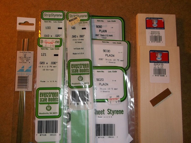
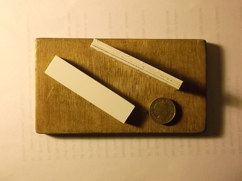
It includes basswood for the hull, plastic sheet of various thicknesses, assorted strip, wood for the propellors, brass rod for the booms and copper wire for the rigging. I will write the instructions as I go along as usual. Additional materials will be required for the base but that need not distract us here. The first stage was to make up units which will become the hull, wings and engine nacelles. The engine nacelles are to be made from three pieces of 60 thou card and one of 20 thou which have been laminated.
Thanks for looking.
This project is being built as part of a Flying Boats Group Build on another site. I usually make small models because I only live in a small house and do not have the space to display large ones. Stevehed introduced me to prototype German giant aircraft of WW1 with his DFW R1 scratch build a couple of years ago, and last year I discovered the Siemens-Schuchert Werke Rs I while looking through photos on the net. I discovered the subject of this build at the same time and knew immediately that I wanted to give it a try. Fortunately the internet has made access to information on these early types much easier than it used to be: in addition there is a Windsock DataFile (no 136) which also contains information and drawings, although the drawings for the machine that I wish to model are at 1/144 scale so I have had to enlarge them to the Correct Scale i.e. 1/72. My intention with this build, as it is with all of my builds, is to demonstrate what can be done by an average modeller with simple tools and a minimum of expensive equipment, and limited skill but some patience! I hope to shape and scrape my way to something that will resemble this:
1000aircraftphotos.com/Contributions/SavinCristian/8377L.jpg
flyingmachines.ru/Images7/Putnam/German_Giants/65-1.jpg
My apologies for not providing a photo but I am not sure about copyright restrictions and I do not wish to bring problems to the site by using pictures without prior permission. These were taken in November 1916 at the Zeppelin shed at Seemoos, Lindau, on Lake Constance where the aircraft was built. I intend to make a small diorama based on the turntable and slipway in front of the shed as shown in these photos so that I can display what will be for me a large model. (The wingspan is approximately 17 1/2 inches: 44 cm and the length 13 inches: 33 cm). I will provide details of the diorama build in the appropriate part of this site in due course. Incidentally the figure in the Homburg hat at the bottom right of the first photo is Claudius Dornier.
I write "resemble the above" because the picture shows the Rs II in its final form with the engines in cowlings and a simple tail unit. I intend to model the machine with the engines in cowlings but with an earlier version of the tail which looked something like this:
flyingmachines.ru/Images7/Putnam/German_Giants/63-2.jpg
Note the large fins and rudders and the biplane elevator. Here the engines are without cowlings: these were added later because the engines ran too cold. The building in the background is the Zeppelin shed at Seemoos.
C. Dornier was working for Graf Zeppelin when in August 1914 he was charged with the design of a number of large flying boats for the Imperial German Navy: the flying boats were to be used to monitor Scapa Flow which was the principal base of the Royal Navy’s Grand Fleet. His Rs I design was a huge biplane with a wingspan of 43.5m: it was constructed largely from steel alloy using airship construction practices. This machine was one of the first all-metal aircraft to be built and flown, when most aircraft were made from wood and linen held together with lots of wire, but it was wrecked in a storm on Lake Constance on 21 December 1915. Dornier's second design was very different from the first and incorporated features which were to characterise subsequent flying boats from this team. They included a very broad hull and a low aspect ratio main plane which was mounted parasol fashion high above the hull. Although the first version had three engines in the hull, these were quickly increased to four and mounted in tandem between the hull and wing, driving push and pull propellors. Small stub wings were fixed to the rear of the hull: on later designs these became full sponsons. The tail unit was on booms which were left uncovered to avoid damage from spray when taxiing. The early booms were made from lattice girders but these were quickly replaced by stronger large diameter steel tube, and the original central fin was replaced by a pair of fins and rudders. The elevator was of biplane form. In the final version of the Rs II the tail boom, rudders and elevator were simplified and it only remained for the design team to change the boom to a single fuselage mounted above the wing on the Rs III for the basic shape of the classic Dornier flying boats of the inter-war and wartime periods to emerge.
Here is my kit for the build: it is not quite complete as I am sure that I will require additional items as I go along:
It includes basswood for the hull, plastic sheet of various thicknesses, assorted strip, wood for the propellors, brass rod for the booms and copper wire for the rigging. I will write the instructions as I go along as usual. Additional materials will be required for the base but that need not distract us here. The first stage was to make up units which will become the hull, wings and engine nacelles. The engine nacelles are to be made from three pieces of 60 thou card and one of 20 thou which have been laminated.
Thanks for looking.
Please Log in to join the conversation.
8 years 7 months ago #128
by Stevef
Replied by Stevef on topic 1/72 Zeppelin-Lindau (Dornier) Rs II scratch build
Evening All,
This is a continuation of the previous post as I had too many links for a single posting.
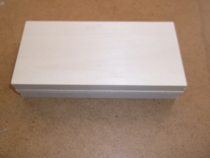
The hull is going to be made from a sandwich of 2 pieces of 1.3cm x 16.6cm x 6.3cm basswood with a sheet 0.7cm thick wood between.
The wings will be made in two sections from three sheets of 60 thou card, laminated, shaped and then butt joined, reinforced with metal pins as on the SSW.
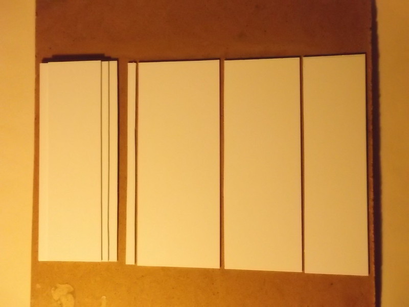
The wing and hull blocks now look like this:
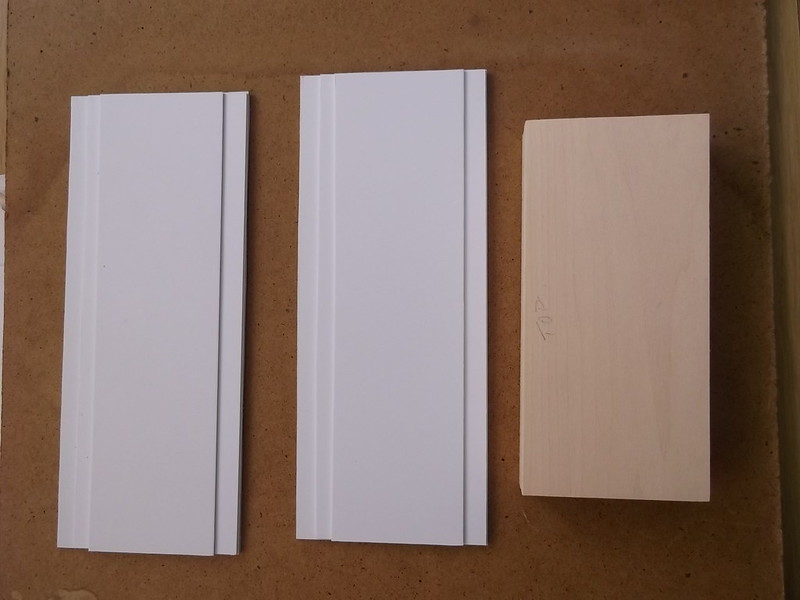
......which means that I can now spend many happy hours scraping and shaping.........
Thanks for looking.
This is a continuation of the previous post as I had too many links for a single posting.
The hull is going to be made from a sandwich of 2 pieces of 1.3cm x 16.6cm x 6.3cm basswood with a sheet 0.7cm thick wood between.
The wings will be made in two sections from three sheets of 60 thou card, laminated, shaped and then butt joined, reinforced with metal pins as on the SSW.
The wing and hull blocks now look like this:
......which means that I can now spend many happy hours scraping and shaping.........
Thanks for looking.
Please Log in to join the conversation.
- Robbo
- Visitor
-

8 years 6 months ago #129
by Robbo
Replied by Robbo on topic 1/72 Zeppelin-Lindau (Dornier) Rs II scratch build
Interesting to see this take shape, completely from scratch? very impressive
Please Log in to join the conversation.
8 years 6 months ago #130
by Stevef
Replied by Stevef on topic 1/72 Zeppelin-Lindau (Dornier) Rs II scratch build
Yes Robbo, this will be completely from scratch as I do not intend to use any aftermarket parts.
Please Log in to join the conversation.
8 years 6 months ago #131
by Stevef
Replied by Stevef on topic 1/72 Zeppelin-Lindau (Dornier) Rs II scratch build
Evening All,
I will post the latest progress in two parts as I have a number of images and these exceed the capacity of the site if I try to post in one.
Before I started I decided that I needed some new tools because I were to shape the hull I was not going to get far with the needle files that I normally use for modelling, so I went out and treated myself to these:
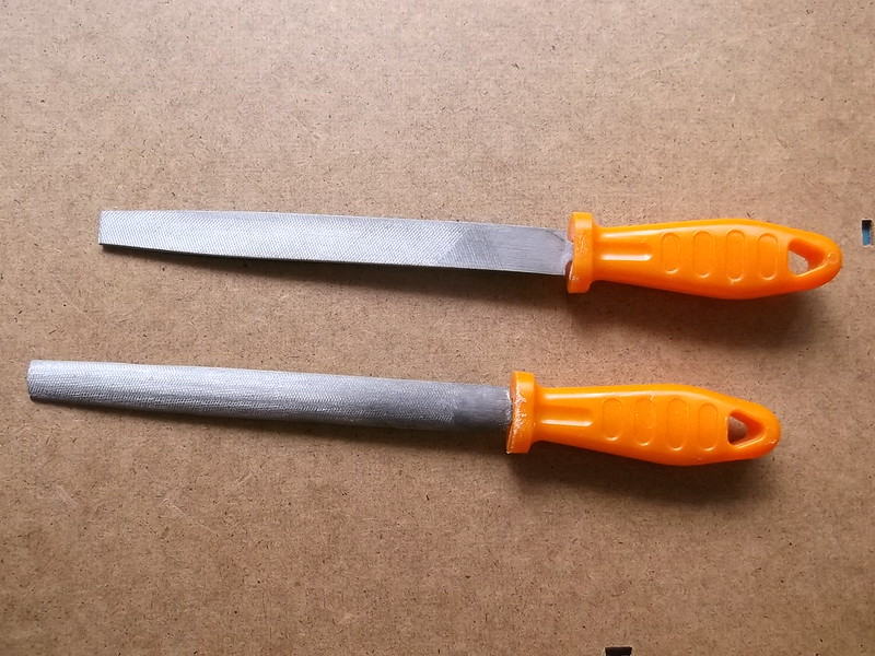
Not the latest in high tech or the most expensive tools around but they were within my limited budget and ideal for the task I had in mind. There was a third round file in the set but I have not had to use that yet, maybe I will later. Bought them from a hardware store round the corner and I was even able to walk to the premises rather than having to drive miles to some horrible industrial park in Kent.
The hull is made from a block of laminated basswood: I have not carved basswood before but would readily do so again if the need arises. It is lovely material to work with: hard but not stiff to file or sand, makes a really good smooth surface which once sealed should be easy to paint, and is robust enough to hold in a vice and not be damaged in the process. I enjoyed making this so far - I hope it continues when I do the extra work later.
Scraping and shaping 1
If you know how to carve shapes from a block of wood I apologise if what follows is tedious and I suggest that you skip this section and just look at the photos as this is intended for those who are not familiar with carving. It is not difficult, it just takes a little time, (or in my case a lot - about 5 hours for what you see at the end of this post). I started by filing the top of the hull to get the correct curved section and then I marked plan on the top surface of the block and sawed away the front corners to make things a little quicker. I also sawed away the section under the nose as I followed the line of the hull side that I had originally drawn and started to file away at the sides to get the correct plan shape. Having almost completed the filing of the sides I realised that I had made a major mistake. I had got carried away with the saw and had cut off the lower half of the bow!! I now intend to use this dud hull as a practice piece for later operations. Back to laminating three pieces of basswood and leaving the lot to dry out overnight under a pile of books: my low tech press.
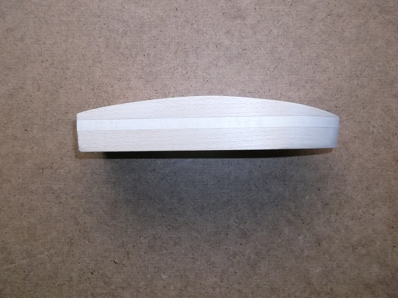
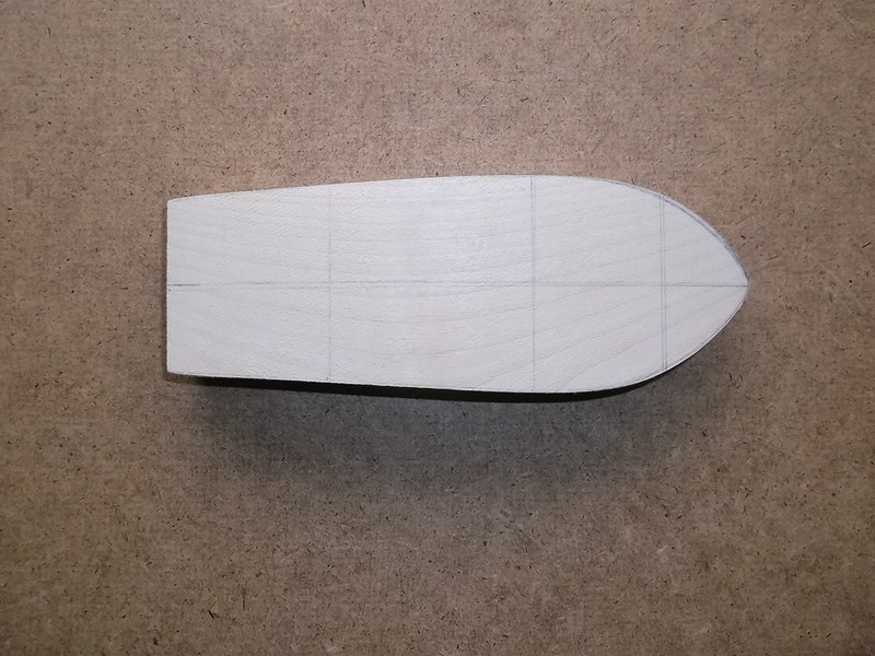
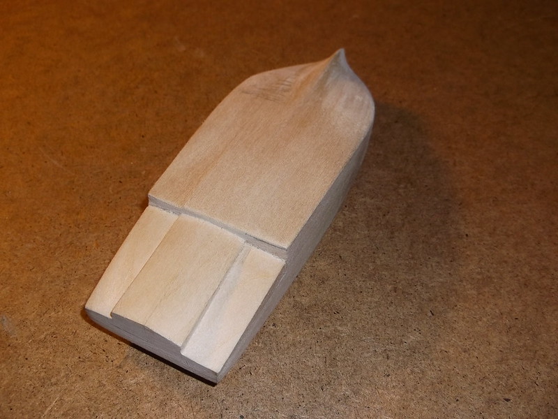
Try number 2: this time I repeated the procedure above to the part where I cut off the corners for the bow section, but this time I made sure that I left the underside well alone. The top of the hull was once again filed to the correct profile:

The plan was marked on the top of the hull and a series of lines drawn at 90 degrees at fixed points to help make sure that I did not get carried away when shaping the sides:
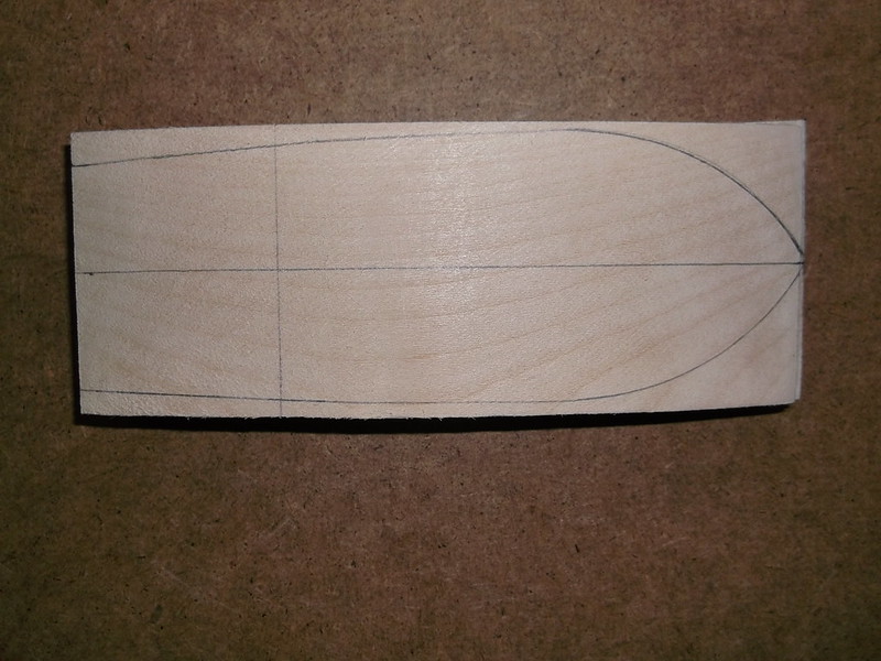
More filing....until this shape was reached:

More in the next post.
Stevef
I will post the latest progress in two parts as I have a number of images and these exceed the capacity of the site if I try to post in one.
Before I started I decided that I needed some new tools because I were to shape the hull I was not going to get far with the needle files that I normally use for modelling, so I went out and treated myself to these:
Not the latest in high tech or the most expensive tools around but they were within my limited budget and ideal for the task I had in mind. There was a third round file in the set but I have not had to use that yet, maybe I will later. Bought them from a hardware store round the corner and I was even able to walk to the premises rather than having to drive miles to some horrible industrial park in Kent.
The hull is made from a block of laminated basswood: I have not carved basswood before but would readily do so again if the need arises. It is lovely material to work with: hard but not stiff to file or sand, makes a really good smooth surface which once sealed should be easy to paint, and is robust enough to hold in a vice and not be damaged in the process. I enjoyed making this so far - I hope it continues when I do the extra work later.
Scraping and shaping 1
If you know how to carve shapes from a block of wood I apologise if what follows is tedious and I suggest that you skip this section and just look at the photos as this is intended for those who are not familiar with carving. It is not difficult, it just takes a little time, (or in my case a lot - about 5 hours for what you see at the end of this post). I started by filing the top of the hull to get the correct curved section and then I marked plan on the top surface of the block and sawed away the front corners to make things a little quicker. I also sawed away the section under the nose as I followed the line of the hull side that I had originally drawn and started to file away at the sides to get the correct plan shape. Having almost completed the filing of the sides I realised that I had made a major mistake. I had got carried away with the saw and had cut off the lower half of the bow!! I now intend to use this dud hull as a practice piece for later operations. Back to laminating three pieces of basswood and leaving the lot to dry out overnight under a pile of books: my low tech press.
Try number 2: this time I repeated the procedure above to the part where I cut off the corners for the bow section, but this time I made sure that I left the underside well alone. The top of the hull was once again filed to the correct profile:
The plan was marked on the top of the hull and a series of lines drawn at 90 degrees at fixed points to help make sure that I did not get carried away when shaping the sides:
More filing....until this shape was reached:
More in the next post.
Stevef
Please Log in to join the conversation.
8 years 6 months ago #132
by Stevef
Replied by Stevef on topic 1/72 Zeppelin-Lindau (Dornier) Rs II scratch build
Scraping and shaping 1 contd.
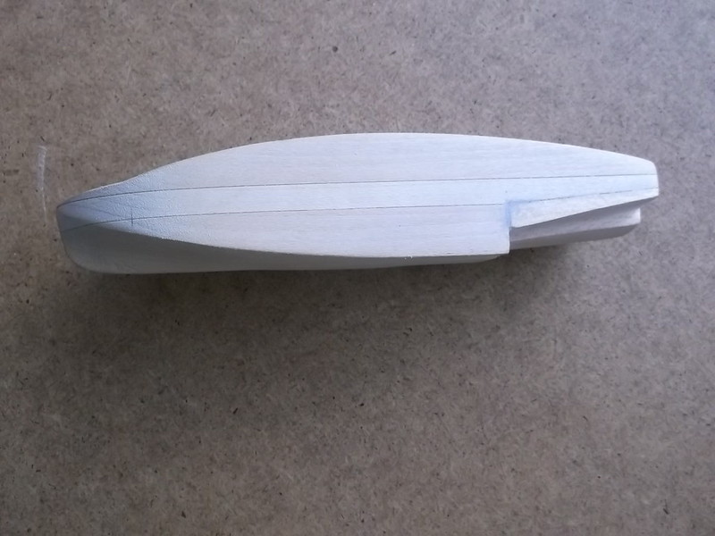
The line running across the front end of the hull becomes important at this stage because there has a subtle curve here which I presume was to allow spray water to drain away quickly. Careful use of the file enabled me to shape the upper surface forward of the line. I worked on each side in turn using photographs to get what I think is the correct profile.
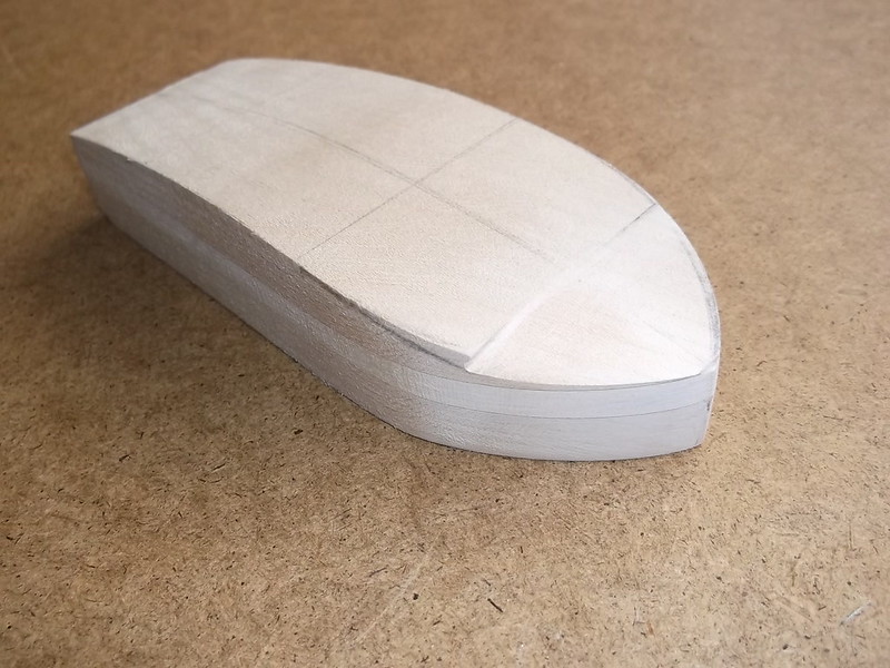
Now for the tricky bit: to get the area of the upper hull to the rear of the line to curve downwards to meet the new side profile forward of the line. The centre line was very important because this is the highest point on the nose of the hull and was used as a guide when drawing the file across the side: more strokes and greater pressure towards the side, almost no pressure and few strokes towards the centre line. I had to work slowly and methodically and towards the end I used coarse grade glass paper to finish the job, again working on each side in turn.
Polishing was done with flour grade glass paper, and the top profile of the hull is finished.
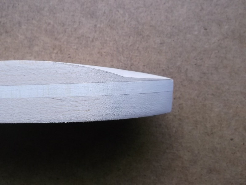
I will make the steps at the rear of the hull next, but before I let myself loose on the new hull I will try out an idea on the old one first. Then I will not have wasted 5 hours of work and another block of wood if something goes wrong.
Now for the tricky bit: to get the area of the upper hull to the rear of the line to curve downwards to meet the new side profile forward of the line. The centre line was very important because this is the highest point on the nose of the hull and was used as a guide when drawing the file across the side: more strokes and greater pressure towards the side, almost no pressure and few strokes towards the centre line. I had to work slowly and methodically and towards the end I used coarse grade glass paper to finish the job, again working on each side in turn.
Polishing was done with flour grade glass paper, and the top profile of the hull is finished.
I will make the steps at the rear of the hull next, but before I let myself loose on the new hull I will try out an idea on the old one first. Then I will not have wasted 5 hours of work and another block of wood if something goes wrong.
Stevef.
The line running across the front end of the hull becomes important at this stage because there has a subtle curve here which I presume was to allow spray water to drain away quickly. Careful use of the file enabled me to shape the upper surface forward of the line. I worked on each side in turn using photographs to get what I think is the correct profile.
Now for the tricky bit: to get the area of the upper hull to the rear of the line to curve downwards to meet the new side profile forward of the line. The centre line was very important because this is the highest point on the nose of the hull and was used as a guide when drawing the file across the side: more strokes and greater pressure towards the side, almost no pressure and few strokes towards the centre line. I had to work slowly and methodically and towards the end I used coarse grade glass paper to finish the job, again working on each side in turn.
Polishing was done with flour grade glass paper, and the top profile of the hull is finished.
I will make the steps at the rear of the hull next, but before I let myself loose on the new hull I will try out an idea on the old one first. Then I will not have wasted 5 hours of work and another block of wood if something goes wrong.
Stevef.
Please Log in to join the conversation.
8 years 6 months ago #133
by Stevef
Replied by Stevef on topic 1/72 Zeppelin-Lindau (Dornier) Rs II scratch build
Evening All,
Once again I am making two posts to explain what I have done because I have put in many pictures. Here is the first half:
I have completed the steps at the rear of the hull, without making a mess of things and having to start all over again. So...
Shaping and scraping 2
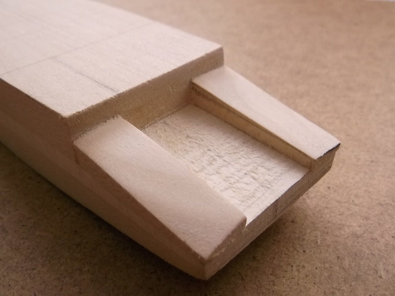
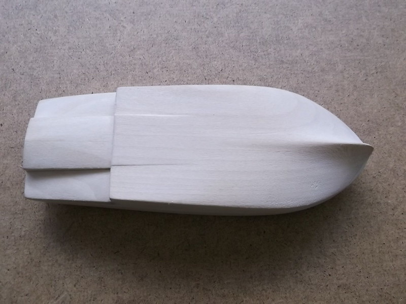
I cut out the whole of the lower rear of the hull - two cuts, one horizontal and one vertical. I then sanded the upper corners smooth as these will be visible when the steps are complete. Two lines were drawn on the horizontal surface to mark where the steps will be.
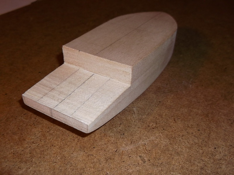
The third line is the centre line and is used to make measurements to keep things symmetrical. The block which I had removed from the hull was cut into three sections, using the dimensions measured from the hull horizontal surface above. The centre section was carefully put to one side and the two side pieces had lines drawn on them to mark the top of the step. This surface is not completely flat: it slopes more at the front end than the rear. One side was then glued to the gap in the hull rear and allowed to dry out overnight. This was then filed down to the lines on each side and polished with fine glass paper to leave a flat surface as shown on this trial block which was my first (failed) attempt to carve the hull:

The third picture shows that the fit on the trial piece was not quite as good as I would have wanted (and achieved) on the real piece: it was after all done to prove a concept and it worked. When the one side step was finished the above operation was repeated for the other side:
Once again I am making two posts to explain what I have done because I have put in many pictures. Here is the first half:
I have completed the steps at the rear of the hull, without making a mess of things and having to start all over again. So...
Shaping and scraping 2
I cut out the whole of the lower rear of the hull - two cuts, one horizontal and one vertical. I then sanded the upper corners smooth as these will be visible when the steps are complete. Two lines were drawn on the horizontal surface to mark where the steps will be.
The third line is the centre line and is used to make measurements to keep things symmetrical. The block which I had removed from the hull was cut into three sections, using the dimensions measured from the hull horizontal surface above. The centre section was carefully put to one side and the two side pieces had lines drawn on them to mark the top of the step. This surface is not completely flat: it slopes more at the front end than the rear. One side was then glued to the gap in the hull rear and allowed to dry out overnight. This was then filed down to the lines on each side and polished with fine glass paper to leave a flat surface as shown on this trial block which was my first (failed) attempt to carve the hull:
The third picture shows that the fit on the trial piece was not quite as good as I would have wanted (and achieved) on the real piece: it was after all done to prove a concept and it worked. When the one side step was finished the above operation was repeated for the other side:
Please Log in to join the conversation.
8 years 6 months ago #134
by Stevef
Replied by Stevef on topic 1/72 Zeppelin-Lindau (Dornier) Rs II scratch build
Evening All,
Evening All,
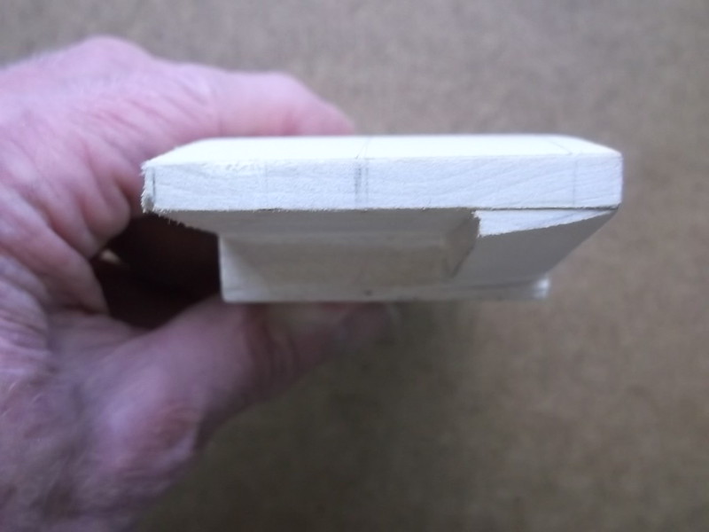
The centre section had to have the sides adjusted with some glass paper to make a really tight fit, but once it could be pushed into the gap I again drew lines on the sides to mark the edges of the hull bottom. I glued the inside surfaces of the hull, tapped the centre piece into place and let the glue set. The top could then be shaped as before with a file, polished with glass paper and the very small gaps filled with putty.

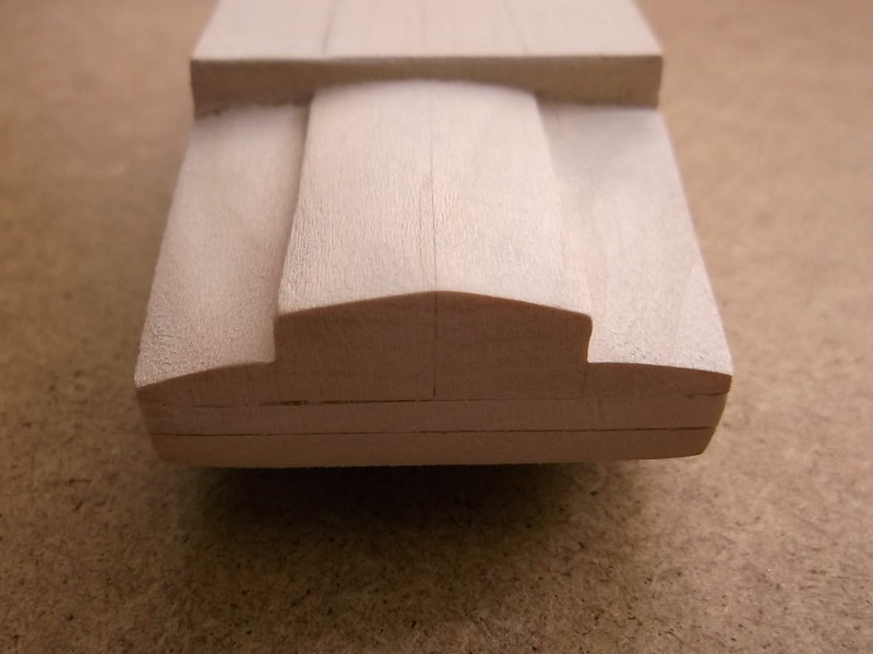
They have now been sanded smooth and I am ready to tackle the hull under the bow. You can see that I have been trying both the round and half round files on the test hull and have concluded that the half round file is the more suitable too. I just hope that I do not make a mess of the next step as there is a lot of time invested in the hull now!
Stevef.
Evening All,
The centre section had to have the sides adjusted with some glass paper to make a really tight fit, but once it could be pushed into the gap I again drew lines on the sides to mark the edges of the hull bottom. I glued the inside surfaces of the hull, tapped the centre piece into place and let the glue set. The top could then be shaped as before with a file, polished with glass paper and the very small gaps filled with putty.
They have now been sanded smooth and I am ready to tackle the hull under the bow. You can see that I have been trying both the round and half round files on the test hull and have concluded that the half round file is the more suitable too. I just hope that I do not make a mess of the next step as there is a lot of time invested in the hull now!
Stevef.
Please Log in to join the conversation.
8 years 6 months ago #135
by Stevef
Replied by Stevef on topic 1/72 Zeppelin-Lindau (Dornier) Rs II scratch build
Evening All,
I am hoping that I can get all of this udate into one post as there are not so many photos this time. So here goes...
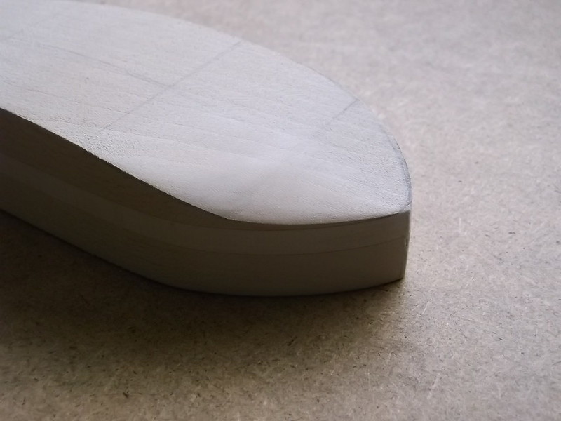
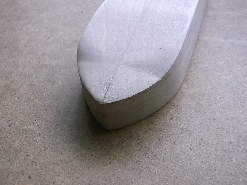
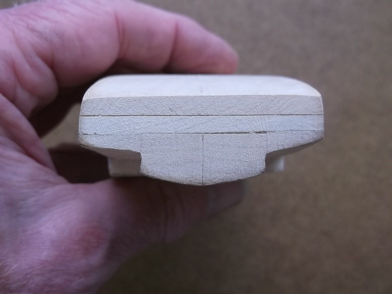
I have completed the scraping and shaping of the bow, and managed to do so without taking off too much material, and I have kept it symmetrical. I do have a card former which was made from one of the section drawings in the DF but the problem is that it only applies to one part of the bow - the rest has to be estimated by Mk 1 eyeball. I used a half round file for this task as the curve is larger and flatter than the round file. This gave a broader curve and made the overall shaping easier, but I also had to take care not to remove too much wood. I had drawn the centre line on the bottom of the hull before I started - this was essential if the bow sides were to be symmetrical. I carved one side first so that it was almost complete, and then I carved the other until it was in the same state. I took out material from the mid point between the centre line on the bottom of the hull, and the line on the side of the hull marking the vertical section. To start with the edge of the wood looked awful but by gradually extending the line of cut laterally in both directions by using the curve of the file blade, and continuing to remove material from the central area, the desired shape gradually appeared. Finally I took a little wood off each side alternately as shown in the photos below, until I judged that the keel was thin enough and the curve was as close as I could get to the card former. I have never shaped a bow before - this was a first attempt, so please be considerate and leave the micrometers in the back pocket when looking at it!
The pencil marks on the port (left) side show where I still need to take off more wood. By marking the area in this way the other areas are not accidentally worn away and the desired shape lost.
This second view shows the marks on the starboard (right) side of the nose where I had previously used the file. This area had also been marked with a pencil as shown above.
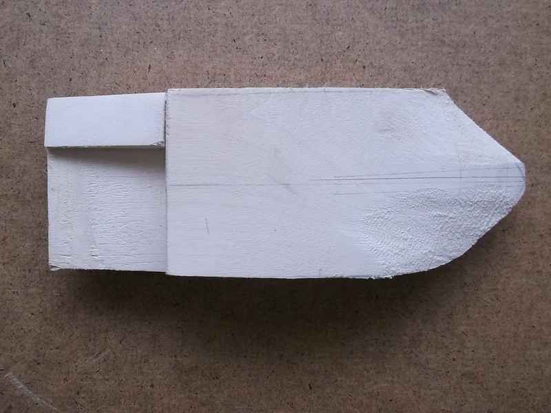
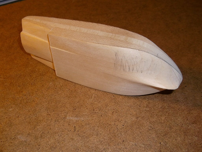
The left and right sides respectively of the completed hull showing the line where the vertical sides meet the planing (under) surface. The marks at the rear are filler used to smooth the joint where I replaced the wood when making the stepped rear as described in the previous post.
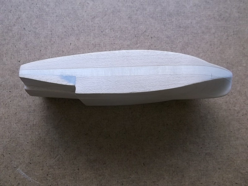
I have also finished scraping the underside of the hull - you will see that there are two small longitudinal steps towards the rear. These were taken down with the flat file by gently putting pressure on the file as I drew it forwards and backwards, following a pencil line that I had marked previously. All of the hull has been polished with fine grade glass paper.
The hull is now semi-complete: I have still to drill out the cockpit opening and add details and then drill approximately 40 holes for various attachments: more on that later. And now for some retro-modelling: I have to fill and seal the wood grain and to do that I will use a very old, and for me well tried, method - a mixture of talcum powder and shrinking dope - a la Airfix Magazine sometime in the early to mid 1960's!
Memories, memories.....
Success!
Thanks for looking.
Stevef.
I am hoping that I can get all of this udate into one post as there are not so many photos this time. So here goes...
I have completed the scraping and shaping of the bow, and managed to do so without taking off too much material, and I have kept it symmetrical. I do have a card former which was made from one of the section drawings in the DF but the problem is that it only applies to one part of the bow - the rest has to be estimated by Mk 1 eyeball. I used a half round file for this task as the curve is larger and flatter than the round file. This gave a broader curve and made the overall shaping easier, but I also had to take care not to remove too much wood. I had drawn the centre line on the bottom of the hull before I started - this was essential if the bow sides were to be symmetrical. I carved one side first so that it was almost complete, and then I carved the other until it was in the same state. I took out material from the mid point between the centre line on the bottom of the hull, and the line on the side of the hull marking the vertical section. To start with the edge of the wood looked awful but by gradually extending the line of cut laterally in both directions by using the curve of the file blade, and continuing to remove material from the central area, the desired shape gradually appeared. Finally I took a little wood off each side alternately as shown in the photos below, until I judged that the keel was thin enough and the curve was as close as I could get to the card former. I have never shaped a bow before - this was a first attempt, so please be considerate and leave the micrometers in the back pocket when looking at it!
The pencil marks on the port (left) side show where I still need to take off more wood. By marking the area in this way the other areas are not accidentally worn away and the desired shape lost.
This second view shows the marks on the starboard (right) side of the nose where I had previously used the file. This area had also been marked with a pencil as shown above.
The left and right sides respectively of the completed hull showing the line where the vertical sides meet the planing (under) surface. The marks at the rear are filler used to smooth the joint where I replaced the wood when making the stepped rear as described in the previous post.
I have also finished scraping the underside of the hull - you will see that there are two small longitudinal steps towards the rear. These were taken down with the flat file by gently putting pressure on the file as I drew it forwards and backwards, following a pencil line that I had marked previously. All of the hull has been polished with fine grade glass paper.
The hull is now semi-complete: I have still to drill out the cockpit opening and add details and then drill approximately 40 holes for various attachments: more on that later. And now for some retro-modelling: I have to fill and seal the wood grain and to do that I will use a very old, and for me well tried, method - a mixture of talcum powder and shrinking dope - a la Airfix Magazine sometime in the early to mid 1960's!
Memories, memories.....
Success!
Thanks for looking.
Stevef.
Please Log in to join the conversation.
8 years 6 months ago #136
by Stevef
Replied by Stevef on topic 1/72 Zeppelin-Lindau (Dornier) Rs II scratch build
Evening All,
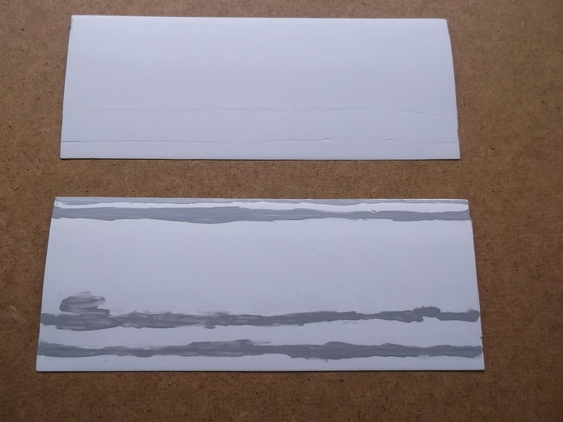
I have decided that as showing a photo of the hull coated with talcum powder and dope filler would not cause much excitement I will move on to the wings. These are to be made from halves of 3 x 60 thou card sheet which has been laminated. These need to be scraped and shaped so:
Scraping and Shaping 4: Wings. I used the flat file again to remove the bulk of the unwanted plastic - rather more on the trailing edge than the leading edge. I have managed to get a fairly sharp trailing edge as per the original aircraft.
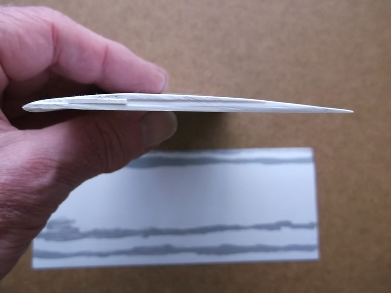
I added a strip of 30 thou card to the undersides of the leading edges and shaped this and the underside of the wing to give an aerofioil section to the wings. The wing halves were then polished with glass paper and the joints between the laminates filled with Mr Surfacer. This in turn was rubbed down and polished:
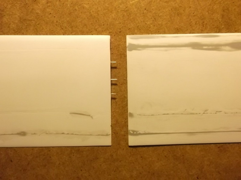
To join the halves I drilled three holes in each half so that I could insert steel pins to reinforce the butt joint. The pins were cut from a paper clip: the wire is rigid enough to make sure that the joint is very strong and will not move when I need to fill it and sand it smooth later.
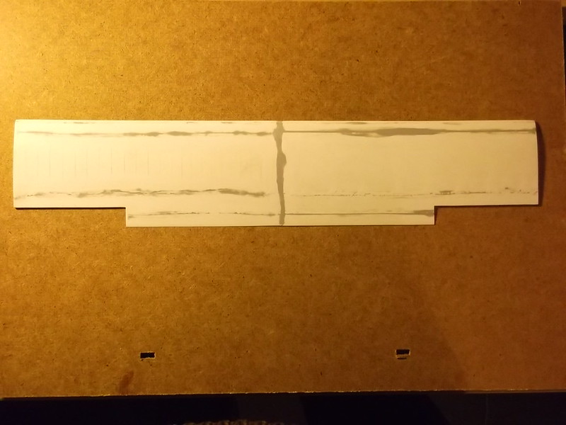
I used CA to hold the pins in place and ordinary cement on the plastic surfaces, having first checked that the halves would line up properly when joined! After it had dried out overnight I liberally coated the joint with Mr Surfacer and vigorously sanded it smooth. I cut out the aeileron gaps and sanded these at the same time so that now the wing structure is complete and awaits the addition of the ribs.
I will add these when the stub wings and elevator surfaces have been made and are ready too.
Thanks for looking.
Stevef.
I have decided that as showing a photo of the hull coated with talcum powder and dope filler would not cause much excitement I will move on to the wings. These are to be made from halves of 3 x 60 thou card sheet which has been laminated. These need to be scraped and shaped so:
Scraping and Shaping 4: Wings. I used the flat file again to remove the bulk of the unwanted plastic - rather more on the trailing edge than the leading edge. I have managed to get a fairly sharp trailing edge as per the original aircraft.
I added a strip of 30 thou card to the undersides of the leading edges and shaped this and the underside of the wing to give an aerofioil section to the wings. The wing halves were then polished with glass paper and the joints between the laminates filled with Mr Surfacer. This in turn was rubbed down and polished:
To join the halves I drilled three holes in each half so that I could insert steel pins to reinforce the butt joint. The pins were cut from a paper clip: the wire is rigid enough to make sure that the joint is very strong and will not move when I need to fill it and sand it smooth later.
I used CA to hold the pins in place and ordinary cement on the plastic surfaces, having first checked that the halves would line up properly when joined! After it had dried out overnight I liberally coated the joint with Mr Surfacer and vigorously sanded it smooth. I cut out the aeileron gaps and sanded these at the same time so that now the wing structure is complete and awaits the addition of the ribs.
I will add these when the stub wings and elevator surfaces have been made and are ready too.
Thanks for looking.
Stevef.
Please Log in to join the conversation.
Time to create page: 0.225 seconds
- You are here:
-
Home

-
Forum
-
Work in progress
-
Airfield
-
Archive
- 1/72 Zeppelin-Lindau (Dornier) Rs II scratch build