No 1A de Haviland: 1/32 stripdown Airco DH 1A
5 years 9 months ago #275
by Stevef
No 1A de Haviland: 1/32 stripdown Airco DH 1A was created by Stevef
Evening All,
“It is a truth universally acknowledged, that every serious aircraft modeller makes pusher biplanes, either from kits, vacuforms, conversions or scratch builds: they are landplanes, floatplanes or flying boats, and can have a combination of tractor and pusher engines. Ideally they should be in God’s Own Scale, but other scales are permitted. When the modeller has built up a suitable collection in the Proper Scale, it is quite appropriate for them to turn to a larger scale and build them in strip-down form.”
Making Real Model Aeroplanes by Stevef, Idontgoto University Press, (in prep).
In keeping with the above, I will attempt to build another large scale (1/32) strip-down pusher, this time the Airco de Haviland D. H. 1A.

When I built the Vickers FB 5 Gunbus I wrote that this was an alternative possibility but because of a lack of information about some parts of the machine, especially the internals of the nacelle, I chose to attempt the Vickers. I am still lacking some information but have come to the conclusion that it probably does not exist. Consequently I intend to use modeller's license and the fact that G. de Haviland helped to design the Royal Aircraft Factory FE 2a: the two machines were remarkably similar in many ways. Given this I intend to construct what I think is a plausible representation - if anyone has contradictory evidence I would be very pleased to have it.
I have already converted one of these from the Airfix 1/72 D.H. 4,
It looks like this:

So I have put together my kit which consists of the usual plastic strip, card, rod, brass rod and bar, wood, thread, etc and some odds and ends from specialist suppliers:

As the engine in the above image is a bit small and the wrong type, I have selected this lovely specimen from WingnutWings:

I had toyed with the idea of making one of these from scratch but decided that I might want to build another model before senility prevents me from doing so. I also used these wheels on the Gunbus and recommend them to anyone building early aircraft in this scale:

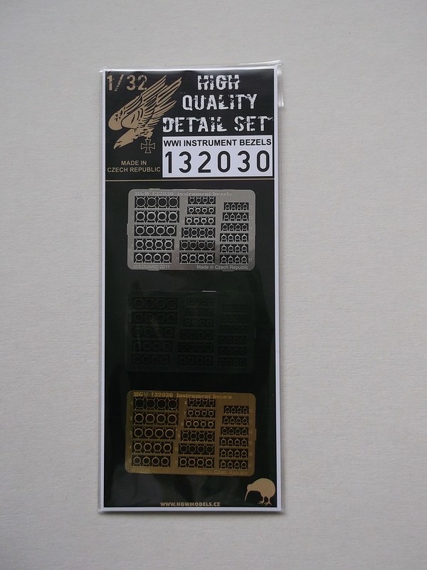
I used these instrument bezels on the Gunbus and although they are barely visible on the model at least I know that they are there together with Airscale transfers for the instrument faces (not illustrated here):
“It is a truth universally acknowledged, that every serious aircraft modeller makes pusher biplanes, either from kits, vacuforms, conversions or scratch builds: they are landplanes, floatplanes or flying boats, and can have a combination of tractor and pusher engines. Ideally they should be in God’s Own Scale, but other scales are permitted. When the modeller has built up a suitable collection in the Proper Scale, it is quite appropriate for them to turn to a larger scale and build them in strip-down form.”
Making Real Model Aeroplanes by Stevef, Idontgoto University Press, (in prep).
In keeping with the above, I will attempt to build another large scale (1/32) strip-down pusher, this time the Airco de Haviland D. H. 1A.

When I built the Vickers FB 5 Gunbus I wrote that this was an alternative possibility but because of a lack of information about some parts of the machine, especially the internals of the nacelle, I chose to attempt the Vickers. I am still lacking some information but have come to the conclusion that it probably does not exist. Consequently I intend to use modeller's license and the fact that G. de Haviland helped to design the Royal Aircraft Factory FE 2a: the two machines were remarkably similar in many ways. Given this I intend to construct what I think is a plausible representation - if anyone has contradictory evidence I would be very pleased to have it.
I have already converted one of these from the Airfix 1/72 D.H. 4,
It looks like this:

So I have put together my kit which consists of the usual plastic strip, card, rod, brass rod and bar, wood, thread, etc and some odds and ends from specialist suppliers:

As the engine in the above image is a bit small and the wrong type, I have selected this lovely specimen from WingnutWings:

I had toyed with the idea of making one of these from scratch but decided that I might want to build another model before senility prevents me from doing so. I also used these wheels on the Gunbus and recommend them to anyone building early aircraft in this scale:

I used these instrument bezels on the Gunbus and although they are barely visible on the model at least I know that they are there together with Airscale transfers for the instrument faces (not illustrated here):

Please Log in to join the conversation.
5 years 9 months ago #276
by Stevef
Replied by Stevef on topic No 1A de Haviland: 1/32 stripdown Airco DH 1A
Another small detail will be provided by resin representations of the pulsometers:

That is enough pre-manufactured material, now to start the real modelling. The Gunbus was a half-strip down model but that presented unforseen problems because the weight is concentrated on one side, making the model inherently unstable and in need of permanent support to stop it leaning. The undercarriage is also not as strong as I would like it to be, so I have decided to build this model as a complete strip down. This means that all of the interior detail in the fuselage nacelle and the engine will be fully exposed, together with the structure of the flying surfaces. I know that there are kits that represent different aircraft in varying degrees of strip down, but as far as I am aware, none of the Airco D.H. 1A.
I have been experimenting with some parts as I was finishing the FE 2d, the first being how to make the wing ribs. There are rather a lot of them and they have to be the same size in two patterns: some with holes and some with slots and holes. To ensure that they are all the same size I am using the following procedure:
a. cut a length of 60 x 180 thou Evergreen strip (top)
b. shape the strip to the shape of the rib. This will be the master strip for all subsequent ribs of this size. (second from top)
c. using the master as a template, cut and shape another piece of plastic strip and mark on with a sharp pencil where the spars pass through (4th from top)
d. drill holes between the lines which mark the spars (bottom)
e. cut out square holes for the brass bar spars (middle):

Complete the rib by drilling holes and cutting the slots as necessary. There are 40 full chord and 29 narrower chord ribs to make for both sets of wings, so I will make some and then work on another part of the model, go back and make some more, repeat etc until they are all made....
I also want to try out another idea which is to use wood laminate for the propellor. I have already commented elsewhere that British propellors were made from laminated mahogony or similar wood and so should be uniformly dark, as on my Gunbus, but I decided to be a little inaccurate on this model and have used two types of wood instead. Strips of laminate were cut to length:

These were glued with Evostick wood glue which dries clear, and the piece put under a press overnight:

Not much chance of that delaminating when it is shaped! First mark out the plan of the propellor and file the wood so that the basic outline of the propellor is made:

I marked on both surfaces where the bosses would be and the curved flat faces between the bosses and the edges of the blades. By carefully filing one face at a time the propellor can be shaped:

As stated this is not strictly accurate as the laminations should be much thinner and darker but most people who look at the model will not be aware of this and I want something a little different.
It may be a little while before the next post because although like others I am currently confined to my home, I have rather a lot of ribs to make and I need to work out the internal structure of the nacelle, and then how to start making that and the internal fittings.
If you have been, thanks for looking.
Stevef.

That is enough pre-manufactured material, now to start the real modelling. The Gunbus was a half-strip down model but that presented unforseen problems because the weight is concentrated on one side, making the model inherently unstable and in need of permanent support to stop it leaning. The undercarriage is also not as strong as I would like it to be, so I have decided to build this model as a complete strip down. This means that all of the interior detail in the fuselage nacelle and the engine will be fully exposed, together with the structure of the flying surfaces. I know that there are kits that represent different aircraft in varying degrees of strip down, but as far as I am aware, none of the Airco D.H. 1A.
I have been experimenting with some parts as I was finishing the FE 2d, the first being how to make the wing ribs. There are rather a lot of them and they have to be the same size in two patterns: some with holes and some with slots and holes. To ensure that they are all the same size I am using the following procedure:
a. cut a length of 60 x 180 thou Evergreen strip (top)
b. shape the strip to the shape of the rib. This will be the master strip for all subsequent ribs of this size. (second from top)
c. using the master as a template, cut and shape another piece of plastic strip and mark on with a sharp pencil where the spars pass through (4th from top)
d. drill holes between the lines which mark the spars (bottom)
e. cut out square holes for the brass bar spars (middle):

Complete the rib by drilling holes and cutting the slots as necessary. There are 40 full chord and 29 narrower chord ribs to make for both sets of wings, so I will make some and then work on another part of the model, go back and make some more, repeat etc until they are all made....
I also want to try out another idea which is to use wood laminate for the propellor. I have already commented elsewhere that British propellors were made from laminated mahogony or similar wood and so should be uniformly dark, as on my Gunbus, but I decided to be a little inaccurate on this model and have used two types of wood instead. Strips of laminate were cut to length:

These were glued with Evostick wood glue which dries clear, and the piece put under a press overnight:

Not much chance of that delaminating when it is shaped! First mark out the plan of the propellor and file the wood so that the basic outline of the propellor is made:

I marked on both surfaces where the bosses would be and the curved flat faces between the bosses and the edges of the blades. By carefully filing one face at a time the propellor can be shaped:

As stated this is not strictly accurate as the laminations should be much thinner and darker but most people who look at the model will not be aware of this and I want something a little different.
It may be a little while before the next post because although like others I am currently confined to my home, I have rather a lot of ribs to make and I need to work out the internal structure of the nacelle, and then how to start making that and the internal fittings.
If you have been, thanks for looking.
Stevef.
Please Log in to join the conversation.
5 years 9 months ago #277
by Stevef
Replied by Stevef on topic No 1A de Haviland: 1/32 stripdown Airco DH 1A
Evening All
I have been informed via another site that pulseometers (small pumps) were only used on rotary engines! So that bit of AM has been stored in the spares box, although I do not have any projects in mind at the moment which will need them.
I have been making ribs - I have to make rather lot - but constantly having to drill holes using a hand chuck has caused strain in my arm so I am having a break from that and have started work on the nacelle instead. I will continue making ribs, but rather than make them all in one go as originally intended, I will make two or three per evening, and hope that I do not lose track of what I have made and what I still need to make. Then I have the riblets to make for the wing leading edges.....
I do not have any detailed information about the nacelle - I have been able to work out some of the framework, where there were engine bearers, fuel tank, some stringers on the sides, the pilot had a seat but the observer probably had a simpler flat folding(?) board, and I know that the nose was metal. Apart from that It is pretty much guesswork. I am using the wonderful drawings of the interior and structure of the FE 2B from the DatatFile No 147 because G de Haviland helped to design that machine and I am sure that he took ideas and incorporated them in the DH 1/1A. So I have made some scale drawings of what I think the design may have looked like but if anyone knows better please tell me soon because I have started to make the nacelle. Deciding what to use took almost as much time as working out what the nacelle may have looked like: I mocked up a side using plastic strip, and guidance for size of material from the FE 2b drawings:

The bottom longeron was deeper than the upper parts and I have decided that the spacing of the verticals is wrong. It has also confirmed to me that it is not practical to join the wing spars to an all plastic structure: the spars will be made from brass bar, and I am not happy about using CA or epoxy to join the spars to a plastic strip. I do not want this to fall apart just when I am at the rigging stage for example. So after yet another morning of working in a crabwise manner towards a solution I decided to make the upper part of the structure from brass bar and just the lower longeron from plastic. My reasoning is that on the FE 2 the lower longeron was wider than the upper parts of the nacelle frame because it was carrying extra weight and therefore was more heavily stressed, so G. de Haviland probably used the same idea in his second pusher. I decided to use 1/16 square brass bar for the upper part of the nacelle and 60 x 80 strip for the lower longerons. The lower longerons will not be carrying much weight so they can be epoxied to the uprights of the nacelle frame. Brass bar was cut and soldered in the usual fashion to make up two sides:

then the top frames were joined to one of the sides followed by the other. In doing this I discovered how easy it is to cause solder to melt when trying to join a new piece which is at 90 degrees to one already soldered. This is a good test of patience I decided, but I did get there in the end:

The observant reader will have noticed that the uprights at the rear of the nacelle were angled forwards to meet the rear spar, and that the front spar was probably bolted to the lower longeron beneath another upright. I intend to use these two uprights as points to solder the model spars: these will make much stronger unions than trying to use epoxy or CA with brass and plastic. Therefore it was imperative that the ends of the two rear uprights were in precisely the right place. This was easy to do - mount two ribs on to two pieces of brass bar which will be used for spars on the model and use them as a guide for spacing the ends of the uprights:

The nacelle frame now looks like this from the front,:

and like this from the side:

Now I can start to make parts for the interior - these will be from plastic for the most part. I will also continue to make more ribs and riblets for the wings....
Thanks for looking.
I have been informed via another site that pulseometers (small pumps) were only used on rotary engines! So that bit of AM has been stored in the spares box, although I do not have any projects in mind at the moment which will need them.
I have been making ribs - I have to make rather lot - but constantly having to drill holes using a hand chuck has caused strain in my arm so I am having a break from that and have started work on the nacelle instead. I will continue making ribs, but rather than make them all in one go as originally intended, I will make two or three per evening, and hope that I do not lose track of what I have made and what I still need to make. Then I have the riblets to make for the wing leading edges.....
I do not have any detailed information about the nacelle - I have been able to work out some of the framework, where there were engine bearers, fuel tank, some stringers on the sides, the pilot had a seat but the observer probably had a simpler flat folding(?) board, and I know that the nose was metal. Apart from that It is pretty much guesswork. I am using the wonderful drawings of the interior and structure of the FE 2B from the DatatFile No 147 because G de Haviland helped to design that machine and I am sure that he took ideas and incorporated them in the DH 1/1A. So I have made some scale drawings of what I think the design may have looked like but if anyone knows better please tell me soon because I have started to make the nacelle. Deciding what to use took almost as much time as working out what the nacelle may have looked like: I mocked up a side using plastic strip, and guidance for size of material from the FE 2b drawings:

The bottom longeron was deeper than the upper parts and I have decided that the spacing of the verticals is wrong. It has also confirmed to me that it is not practical to join the wing spars to an all plastic structure: the spars will be made from brass bar, and I am not happy about using CA or epoxy to join the spars to a plastic strip. I do not want this to fall apart just when I am at the rigging stage for example. So after yet another morning of working in a crabwise manner towards a solution I decided to make the upper part of the structure from brass bar and just the lower longeron from plastic. My reasoning is that on the FE 2 the lower longeron was wider than the upper parts of the nacelle frame because it was carrying extra weight and therefore was more heavily stressed, so G. de Haviland probably used the same idea in his second pusher. I decided to use 1/16 square brass bar for the upper part of the nacelle and 60 x 80 strip for the lower longerons. The lower longerons will not be carrying much weight so they can be epoxied to the uprights of the nacelle frame. Brass bar was cut and soldered in the usual fashion to make up two sides:

then the top frames were joined to one of the sides followed by the other. In doing this I discovered how easy it is to cause solder to melt when trying to join a new piece which is at 90 degrees to one already soldered. This is a good test of patience I decided, but I did get there in the end:

The observant reader will have noticed that the uprights at the rear of the nacelle were angled forwards to meet the rear spar, and that the front spar was probably bolted to the lower longeron beneath another upright. I intend to use these two uprights as points to solder the model spars: these will make much stronger unions than trying to use epoxy or CA with brass and plastic. Therefore it was imperative that the ends of the two rear uprights were in precisely the right place. This was easy to do - mount two ribs on to two pieces of brass bar which will be used for spars on the model and use them as a guide for spacing the ends of the uprights:

The nacelle frame now looks like this from the front,:

and like this from the side:

Now I can start to make parts for the interior - these will be from plastic for the most part. I will also continue to make more ribs and riblets for the wings....
Thanks for looking.
Please Log in to join the conversation.
5 years 9 months ago #278
by Stevef
Replied by Stevef on topic No 1A de Haviland: 1/32 stripdown Airco DH 1A
Evening All,
I have already described how G. de Haviland had been heavily involved in the design of the RAF FE 2a and later 2b before he left the Royal Aircraft Factory to join the Aircraft Manufacturing Company as the chief designer. I have also stated that I do not have drawings of the interior of the DH 1/1A, but both the FE 2a and the DH 1 were powered by 100hp Renault engines, and the FE 2b and DH 1A were powered by 120 hp Beardmore engines. I spent a morning and more earlier this week trying to make plausible drawings for the interior of the DH 1A based loosely on the FE 2b and thought that the engine installation should be similar on both the 2b and 1A. One of the key differences between the RAF and DH machines was that the former had a bulbous forward nacelle which tapered rearwards whereas the DH nacelle had parallel sides. The engines in both machines were mounted on frames inside the rear nacelle. It was only today when I closely compared the drawings of the two nacelles that I realised just how similar they were - even down to the length! Then the penny dropped! The DH 1A was almost a copy of the FE 2b although de Haviland made some modifications based on what he must have learned from the test flights of the prototype FE 2b. Now I have worked out without much difficulty the probable construction of the engine mounts and fuel tank, radiator installation, etc in the rear of the DH 1A and it must have been very similar to the FE. I suspect that the same applied to the cockpits - after all why try to reinvent the wheel?
This means that I have had to modify the fuselage frame somewhat: I have taken out the rear upper cross member and installed two extra vertical supports at the rear. These vertical supports would have been anchor points for cross members which were below the engine, which in turn would have carried two longerons on which the sides of the engine rested - just like the FE 2b! Doh!! The horizontal pieces and engine bearer longerons will be added from plastic strip later - they can be held with CA as they will only be supporting a plastic engine, so the main fuselage frame now looks like this:

Now I can fit the engine and I know roughly where the fuel tank will go, so I think that I have worked out the key elements of the interior and can now make the different parts. Sometimes it is only by doing something that the blindingly obvious becomes visible!
I have been fiddling with the engine in order to work out the precise dimensions and location of the bearers, and discovered that the parts tree for the Wingnutwings engine does not have an oil tank or exhaust pipe. I made up an oil tank from a piece of thick sprue and have found another piece of the correct diameter for the exhaust pipe, which I will make later. I have also made the blanks for the radiator from a sandwich of 2 x 80 thou card. I am trying to think about what to use to represent the mesh on the front and rear of the radiator - if anyone has any ideas I would be pleased to read about them. In the meantime here are the radiator blank, oil tank, lower part of the engine and frame:
The second picture shows that the parts will fit as they should when the various sticking out bits on the rear, (forward end in the photo - because the engine was mounted as a pusher the front end of the engine is at the rear of the aircraft), are put into place later.
More to come if you have not lost interest already.
Stevef.
I have already described how G. de Haviland had been heavily involved in the design of the RAF FE 2a and later 2b before he left the Royal Aircraft Factory to join the Aircraft Manufacturing Company as the chief designer. I have also stated that I do not have drawings of the interior of the DH 1/1A, but both the FE 2a and the DH 1 were powered by 100hp Renault engines, and the FE 2b and DH 1A were powered by 120 hp Beardmore engines. I spent a morning and more earlier this week trying to make plausible drawings for the interior of the DH 1A based loosely on the FE 2b and thought that the engine installation should be similar on both the 2b and 1A. One of the key differences between the RAF and DH machines was that the former had a bulbous forward nacelle which tapered rearwards whereas the DH nacelle had parallel sides. The engines in both machines were mounted on frames inside the rear nacelle. It was only today when I closely compared the drawings of the two nacelles that I realised just how similar they were - even down to the length! Then the penny dropped! The DH 1A was almost a copy of the FE 2b although de Haviland made some modifications based on what he must have learned from the test flights of the prototype FE 2b. Now I have worked out without much difficulty the probable construction of the engine mounts and fuel tank, radiator installation, etc in the rear of the DH 1A and it must have been very similar to the FE. I suspect that the same applied to the cockpits - after all why try to reinvent the wheel?
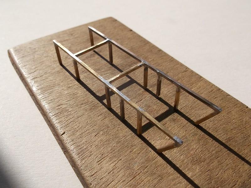
This means that I have had to modify the fuselage frame somewhat: I have taken out the rear upper cross member and installed two extra vertical supports at the rear. These vertical supports would have been anchor points for cross members which were below the engine, which in turn would have carried two longerons on which the sides of the engine rested - just like the FE 2b! Doh!! The horizontal pieces and engine bearer longerons will be added from plastic strip later - they can be held with CA as they will only be supporting a plastic engine, so the main fuselage frame now looks like this:


Now I can fit the engine and I know roughly where the fuel tank will go, so I think that I have worked out the key elements of the interior and can now make the different parts. Sometimes it is only by doing something that the blindingly obvious becomes visible!
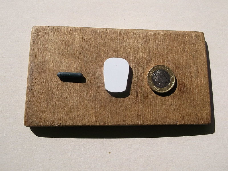
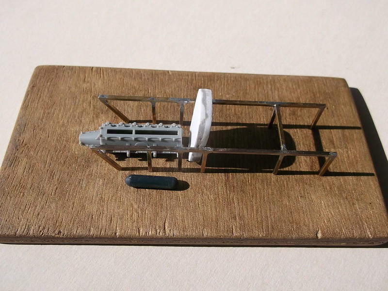
I have been fiddling with the engine in order to work out the precise dimensions and location of the bearers, and discovered that the parts tree for the Wingnutwings engine does not have an oil tank or exhaust pipe. I made up an oil tank from a piece of thick sprue and have found another piece of the correct diameter for the exhaust pipe, which I will make later. I have also made the blanks for the radiator from a sandwich of 2 x 80 thou card. I am trying to think about what to use to represent the mesh on the front and rear of the radiator - if anyone has any ideas I would be pleased to read about them. In the meantime here are the radiator blank, oil tank, lower part of the engine and frame:


The second picture shows that the parts will fit as they should when the various sticking out bits on the rear, (forward end in the photo - because the engine was mounted as a pusher the front end of the engine is at the rear of the aircraft), are put into place later.
More to come if you have not lost interest already.
Stevef.
Please Log in to join the conversation.
5 years 9 months ago #280
by steve.s
Replied by steve.s on topic No 1A de Haviland: 1/32 stripdown Airco DH 1A
Just amazing Steve and the brass solder work is nice to see.
Please Log in to join the conversation.
5 years 9 months ago #281
by Stevef
Replied by Stevef on topic No 1A de Haviland: 1/32 stripdown Airco DH 1A
Evening All
Thanks Steve for the kind comment. More soldering will follow in a later post, but not this one!
The snail continues to move forwards - just. I am still in the process of making the wing ribs - and there seems to be plenty of them! However they are not very photogenic, (see one and you have seen them all), so not much to show there. In between times I have been working on parts of the cockpit interiors which are modelled on the FE 2b for reasons given in the previous post and form the subject of this update.
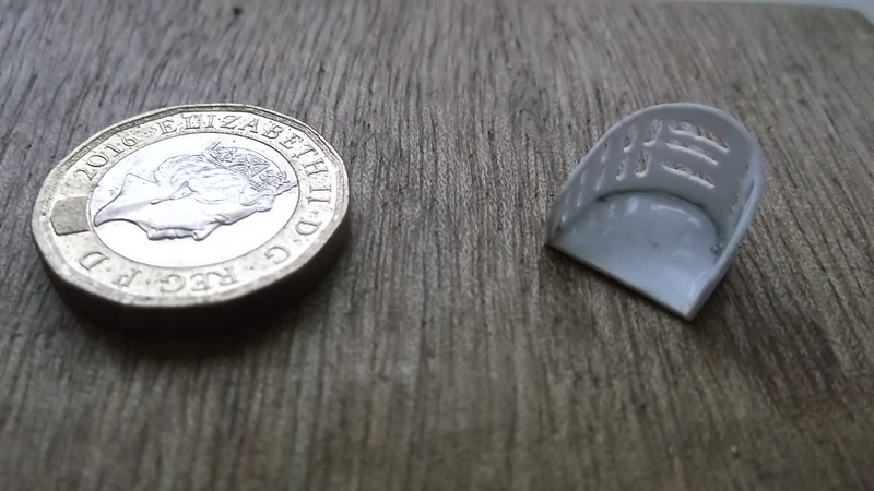
First up is the pilot's seat. These were constructed from aluminium and had holes and slots to make them lighter. I used a piece of 30 thou card for the flat and 20 thou for the back. These were joined with liquid cement - in two stages so that stage one involved half of the seat back only. This was held while the cement dried. The the second half could be pulled around the curve of the seat rear and cemented and held with an old hair clip. The result was that the back was properly aligned with the seat. Only when this was really set did I proceed to drill the holes in the sides and the slots in the rear:
Next was the fuel tank. This was a 35 gallon container - the same as on the FE 2b so I was able to use the 1/32 scale drawings in the DataFile no 147 to work out both the size and shape. A piece of 20 thou card formed the ends and body, and three 30 thou formers were made to strengthen it. The faces of the 20 thou end pieces were embossed by using the blunt end of a nail file. These were cemented to two of the 30 thou formers. The formers were cemented on to the centre of the card which will form the body of the tank:
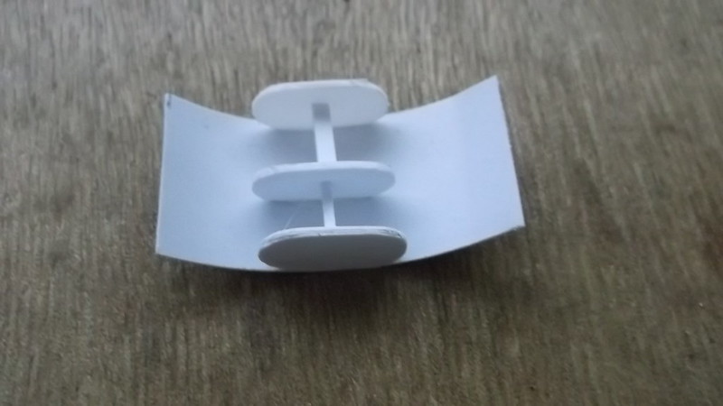
Note the same method was used here as for the pilot's seat - only part of the unit was made so that the formers could be rigidly attached to the card body. When these were properly set the card could be wrapped around half of the formers and held while the cement set. Finally the other side of the card was bent around, excess card cut off and the remainder cemented into place and held until it too had set. A little filler in the gaps and all was finished except for the filler pipe:
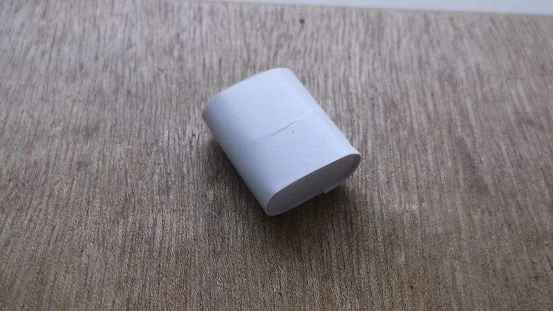
The exhaust pipe was made from a piece of sprue - it came from the same piece as the oil tank described in an earlier post. I have still to drill the exit holes in the end and make the pipes which will connect it to the top of the engine cylinders:

The pilot's seat was probably fixed via runners to a box structure from which protruded rudder foot boards. The box was easily constructed from card as were the rudder foot boards. The rudder bar pivoted on a small pedestal: this was made from 60 thou card. I will make a rudder bar later form a piece of plastic strip. There was a bulkhead between the pilot and observer cockpits: I modelled mine on the FE 2b and initially made it in one piece. A hole was later cut in the lower part which allowed the pilot's legs to pass through to operate the rudder bar: a box would have covered the pilot's feet and formed a seat for the observer as per the FE 2b, although the shape of the de Haviland seat appears to have been different as shown in photo 28 in DataFile 148. This seat, and the floor of the observer's cockpit will be made later as I need to make these parts to fit and can only do so when I have assembled more of the nacelle structures.

The image above shows from left to right:
the bulkhead between the pilot and observer cockpits prior to finishing;
the box for the pilot's seat;
the rudder foot boards and pedestal for the rudder bar;
the pilot's seat.
I made a compass from another small piece of sprue and an instrument panel from 20 thou card, which I scored and bent. A small semicircular platform will support the instrument panel which will sit in front of the upper part of the bulkhead between the pilot and observer. I have also made two semicircles from brass rod which formed a frame for nose cone on the original aircraft: these are waiting to be attached to the main nacelle frame: the upper (smaller) one will be soldered in place later. The parts have been set alongside or in the nacelle frame in the next images but there is an error because I think that I have put the fuel tank filler pipe in the wrong place! I am still not sure where it should properly be but I am inclined to think that it should extend forward because there were two access doors on the sides of the nacelle just behind the pilot's cockpit: if this was the position the pipe would have been rather long but the only rear view of the aircraft in the DataFile 147 shows no sign of any pipe at the rear.


If you have been, thanks for looking.
Stevef.
Thanks Steve for the kind comment. More soldering will follow in a later post, but not this one!
The snail continues to move forwards - just. I am still in the process of making the wing ribs - and there seems to be plenty of them! However they are not very photogenic, (see one and you have seen them all), so not much to show there. In between times I have been working on parts of the cockpit interiors which are modelled on the FE 2b for reasons given in the previous post and form the subject of this update.
First up is the pilot's seat. These were constructed from aluminium and had holes and slots to make them lighter. I used a piece of 30 thou card for the flat and 20 thou for the back. These were joined with liquid cement - in two stages so that stage one involved half of the seat back only. This was held while the cement dried. The the second half could be pulled around the curve of the seat rear and cemented and held with an old hair clip. The result was that the back was properly aligned with the seat. Only when this was really set did I proceed to drill the holes in the sides and the slots in the rear:

Next was the fuel tank. This was a 35 gallon container - the same as on the FE 2b so I was able to use the 1/32 scale drawings in the DataFile no 147 to work out both the size and shape. A piece of 20 thou card formed the ends and body, and three 30 thou formers were made to strengthen it. The faces of the 20 thou end pieces were embossed by using the blunt end of a nail file. These were cemented to two of the 30 thou formers. The formers were cemented on to the centre of the card which will form the body of the tank:

Note the same method was used here as for the pilot's seat - only part of the unit was made so that the formers could be rigidly attached to the card body. When these were properly set the card could be wrapped around half of the formers and held while the cement set. Finally the other side of the card was bent around, excess card cut off and the remainder cemented into place and held until it too had set. A little filler in the gaps and all was finished except for the filler pipe:

The exhaust pipe was made from a piece of sprue - it came from the same piece as the oil tank described in an earlier post. I have still to drill the exit holes in the end and make the pipes which will connect it to the top of the engine cylinders:

The pilot's seat was probably fixed via runners to a box structure from which protruded rudder foot boards. The box was easily constructed from card as were the rudder foot boards. The rudder bar pivoted on a small pedestal: this was made from 60 thou card. I will make a rudder bar later form a piece of plastic strip. There was a bulkhead between the pilot and observer cockpits: I modelled mine on the FE 2b and initially made it in one piece. A hole was later cut in the lower part which allowed the pilot's legs to pass through to operate the rudder bar: a box would have covered the pilot's feet and formed a seat for the observer as per the FE 2b, although the shape of the de Haviland seat appears to have been different as shown in photo 28 in DataFile 148. This seat, and the floor of the observer's cockpit will be made later as I need to make these parts to fit and can only do so when I have assembled more of the nacelle structures.

The image above shows from left to right:
the bulkhead between the pilot and observer cockpits prior to finishing;
the box for the pilot's seat;
the rudder foot boards and pedestal for the rudder bar;
the pilot's seat.
I made a compass from another small piece of sprue and an instrument panel from 20 thou card, which I scored and bent. A small semicircular platform will support the instrument panel which will sit in front of the upper part of the bulkhead between the pilot and observer. I have also made two semicircles from brass rod which formed a frame for nose cone on the original aircraft: these are waiting to be attached to the main nacelle frame: the upper (smaller) one will be soldered in place later. The parts have been set alongside or in the nacelle frame in the next images but there is an error because I think that I have put the fuel tank filler pipe in the wrong place! I am still not sure where it should properly be but I am inclined to think that it should extend forward because there were two access doors on the sides of the nacelle just behind the pilot's cockpit: if this was the position the pipe would have been rather long but the only rear view of the aircraft in the DataFile 147 shows no sign of any pipe at the rear.


If you have been, thanks for looking.
Stevef.
Please Log in to join the conversation.
5 years 8 months ago - 5 years 8 months ago #282
by Stevef
Replied by Stevef on topic No 1A de Haviland: 1/32 stripdown Airco DH 1A
Evening All,
Before I solder the lower wing spars to the nacelle frame I want to make as much of the nacelle interior as possible so that I can align the different parts and make sure that they all fit together when I come to the assembly stage. While the nacelle frame is small it is easily handled and unlikely to be damaged - with the spars attached it becomes a completely different matter. This week I have been making up and detailing the engine.
I am using the excellent Wingnut Wings Beardmore engine which is very good but lacks detail so I have cribbed ideas from Lance Carroll's FE 2b build on ww1aircraftmodels.com.
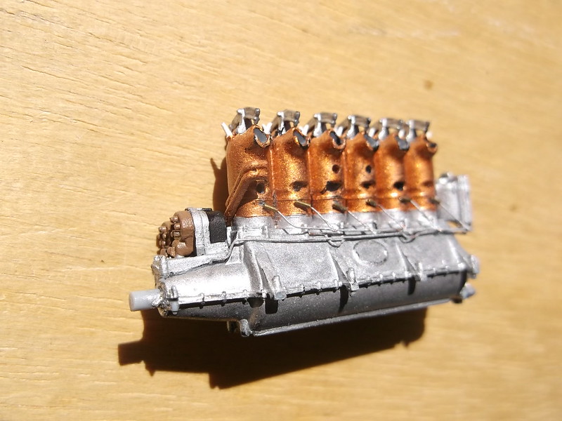
I started by adding the cylinders to the sump and then painting both, followed by the rocker arms and push rods, oil and water pumps and cam drive:


Apologies for the poor quality of the second image: I am not very good with macro shots. The oil lines from the oil pump to the bottom of the cylinders were added from copper wire and 0.3mm brass tube - all CA'd into place. The oil inlets on the kit cylinders had been removed beforehand. The magnetos were added to the front of the engine:

The water inlet pipe and ignition wire conduit were added and then I could install the ignition wires to the spark plugs:

and the ignition wires from the magnetos to the wire conduit pipes:
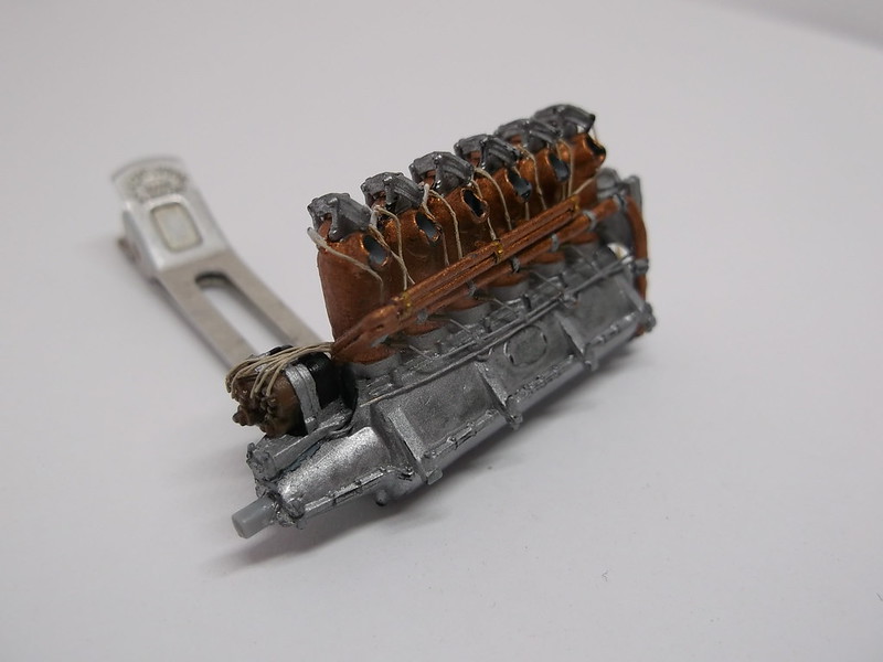
Before I solder the lower wing spars to the nacelle frame I want to make as much of the nacelle interior as possible so that I can align the different parts and make sure that they all fit together when I come to the assembly stage. While the nacelle frame is small it is easily handled and unlikely to be damaged - with the spars attached it becomes a completely different matter. This week I have been making up and detailing the engine.
I am using the excellent Wingnut Wings Beardmore engine which is very good but lacks detail so I have cribbed ideas from Lance Carroll's FE 2b build on ww1aircraftmodels.com.
I started by adding the cylinders to the sump and then painting both, followed by the rocker arms and push rods, oil and water pumps and cam drive:


Apologies for the poor quality of the second image: I am not very good with macro shots. The oil lines from the oil pump to the bottom of the cylinders were added from copper wire and 0.3mm brass tube - all CA'd into place. The oil inlets on the kit cylinders had been removed beforehand. The magnetos were added to the front of the engine:


The water inlet pipe and ignition wire conduit were added and then I could install the ignition wires to the spark plugs:

and the ignition wires from the magnetos to the wire conduit pipes:

Last edit: 5 years 8 months ago by Stevef.
Please Log in to join the conversation.
5 years 8 months ago #283
by Stevef
Replied by Stevef on topic No 1A de Haviland: 1/32 stripdown Airco DH 1A
I do not normally add much evidence of wear to my models - I find it very difficult to achieve the correct "look" but on the engine I feel that a little oil and grime is in order, so I mixed a wash of Humbrol dark earth and a touch of black and hoped for the best when I brushed it on to the engine. It has certainly taken the shine off the copper cylinders and aluminium sump:
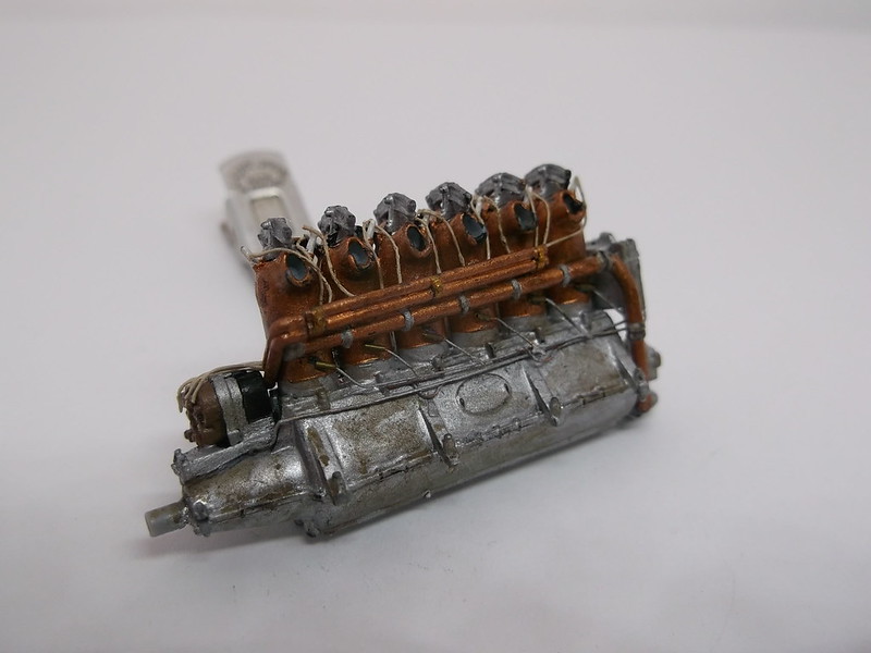

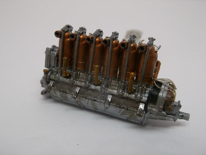
I have still to add oil pipes and control lines to the carburettor and petrol pipe unit, but will not do this until the engine is almost ready to be placed on the nacelle frame as these parts will be both delicate and need to attach to the frame.

Instead I have been working on the exhaust pipe and oil tank which are not included in the engine kit. I had made both units from sprue and now I have drilled a hole right through the oil tank so that I can insert and bend to shape a filler/feed pipe from 30 thou rod. I have also drilled the exhaust pipe outlet holes at its rear end and the inlet pipes for 40 thou rod into which the exhaust stubs will eventually be fitted. The oil tank was mounted on the port (left) side of the engine below the exhaust pipe but I cannot make the support arms until the engine is ready to be mounted on the frame in the nacelle.

While I was performing a dry run aligning the engine with the water outlet pipe to the radiator I realised that the radiator which I have already made was based on the FE 2b whereas the DH 1A had a smaller rectangular radiator! A new one will be made shortly.....
Thanks for looking.
Stevef.


I have still to add oil pipes and control lines to the carburettor and petrol pipe unit, but will not do this until the engine is almost ready to be placed on the nacelle frame as these parts will be both delicate and need to attach to the frame.

Instead I have been working on the exhaust pipe and oil tank which are not included in the engine kit. I had made both units from sprue and now I have drilled a hole right through the oil tank so that I can insert and bend to shape a filler/feed pipe from 30 thou rod. I have also drilled the exhaust pipe outlet holes at its rear end and the inlet pipes for 40 thou rod into which the exhaust stubs will eventually be fitted. The oil tank was mounted on the port (left) side of the engine below the exhaust pipe but I cannot make the support arms until the engine is ready to be mounted on the frame in the nacelle.

While I was performing a dry run aligning the engine with the water outlet pipe to the radiator I realised that the radiator which I have already made was based on the FE 2b whereas the DH 1A had a smaller rectangular radiator! A new one will be made shortly.....
Thanks for looking.
Stevef.
Please Log in to join the conversation.
5 years 8 months ago #284
by Stevef
Replied by Stevef on topic No 1A de Haviland: 1/32 stripdown Airco DH 1A
Evening All,
I have finished the ribs at last - some have taken three attempts to get right - some have holes, some holes and slots, some triangular slots and no hole, some triangular slots and hole....and the combinations were driving me mad as I would shape a rib and then cut/drill the wrong shapes in the wrong places. The tedium of repeating the same operations over and over and the different combinations of slots and holes meant that my concentration lapsed and so mistakes were made. At least the compression ribs, (the short riblets on the leading edges of the wings between the main ribs), were all the same - all 50 of them! Here are a few:

Some of these look a little rough but they have since been cleaned up enough that any small deficiencies can be concealed beneath a coat of paint!!
While I was fiddling and cursing with the ribs I occasionally took a little time to make some other parts. First off was a new radiator, because the first one I had made was for an FE 2: while the DH 1A had some features in common with the FE, the radiator was not one of them! I made a new one from laminated card and a small piece of Eduard etch kindly given to me by a fellow modeller. The radiator faces were painted black before the grille was CA'd into place and the sides of the radiator added from 10thou card:

The FE radiator blank is on the right above - why the DH 1A was smaller I do not know because they had to cool the same engine (120 hp Beardmore).
The DH 1A had a gravity tank under the top wing. It was triangular in shape and I made mine from scrap card. I used small pieces of strip to reinforce the corners and ensure that the sides and front faces were square with the top and bottom surfaces. A small piece of rod blocked the sharp end and allowed me to clean that up with filler:

Another part which needed correcting was the oil tank. Formerly I had made a cylindrical tank - again as per FE but close inspection of the drawings and photos showed that the oil tank on the DH 1A was a different shape. (I had seen this feature before but had thought that it was a protective plate between the tank and exhaust pipe. (How wrong!) This too was fashioned from laminated card. The fuel and new oil tanks look like this:

The oil tank on FE machines was sometimes tinned and sometimes painted black. Photos of the DH1A oil tank are rare, and it is not clear whether the tanks were grey or tinned metal on such photos as I can find. The same applies to the fuel tank. As I am modelling a strip down machine I decided to paint both aluminium:

Having finished (well almost), the ribs I thought that I would make a few more parts before I solder the lower wing spars to the nacelle frame, because when that is done i will have a large, fragile and awkward piece to put in a safe place when I am not working on it. Then I will only have to make a few parts to fit as I am assembling the model. So I carved and shaped the struts for wings, cabanes, booms, undercarriage and wing skids from wood. I used wood laminate: I glued some sheets together to get a suitable thickness. All of the parts except the control horns are slightly oversize so that I can cut them to fit exactly during the assembly process. The control horns were made from the same material:

They are top left - spreader bar for the undercarriage, bottom left undercarriage legs, (the 4th from left is much too large and will need cutting down), wing and cabane struts, (again the cabanes are too long), wing skids, (the small rough pieces will form the horizontal pieces later), and top right some of the control horns. These will all be clear varnished later before fixing into place.
I have finished the ribs at last - some have taken three attempts to get right - some have holes, some holes and slots, some triangular slots and no hole, some triangular slots and hole....and the combinations were driving me mad as I would shape a rib and then cut/drill the wrong shapes in the wrong places. The tedium of repeating the same operations over and over and the different combinations of slots and holes meant that my concentration lapsed and so mistakes were made. At least the compression ribs, (the short riblets on the leading edges of the wings between the main ribs), were all the same - all 50 of them! Here are a few:

Some of these look a little rough but they have since been cleaned up enough that any small deficiencies can be concealed beneath a coat of paint!!
While I was fiddling and cursing with the ribs I occasionally took a little time to make some other parts. First off was a new radiator, because the first one I had made was for an FE 2: while the DH 1A had some features in common with the FE, the radiator was not one of them! I made a new one from laminated card and a small piece of Eduard etch kindly given to me by a fellow modeller. The radiator faces were painted black before the grille was CA'd into place and the sides of the radiator added from 10thou card:

The FE radiator blank is on the right above - why the DH 1A was smaller I do not know because they had to cool the same engine (120 hp Beardmore).
The DH 1A had a gravity tank under the top wing. It was triangular in shape and I made mine from scrap card. I used small pieces of strip to reinforce the corners and ensure that the sides and front faces were square with the top and bottom surfaces. A small piece of rod blocked the sharp end and allowed me to clean that up with filler:

Another part which needed correcting was the oil tank. Formerly I had made a cylindrical tank - again as per FE but close inspection of the drawings and photos showed that the oil tank on the DH 1A was a different shape. (I had seen this feature before but had thought that it was a protective plate between the tank and exhaust pipe. (How wrong!) This too was fashioned from laminated card. The fuel and new oil tanks look like this:

The oil tank on FE machines was sometimes tinned and sometimes painted black. Photos of the DH1A oil tank are rare, and it is not clear whether the tanks were grey or tinned metal on such photos as I can find. The same applies to the fuel tank. As I am modelling a strip down machine I decided to paint both aluminium:

Having finished (well almost), the ribs I thought that I would make a few more parts before I solder the lower wing spars to the nacelle frame, because when that is done i will have a large, fragile and awkward piece to put in a safe place when I am not working on it. Then I will only have to make a few parts to fit as I am assembling the model. So I carved and shaped the struts for wings, cabanes, booms, undercarriage and wing skids from wood. I used wood laminate: I glued some sheets together to get a suitable thickness. All of the parts except the control horns are slightly oversize so that I can cut them to fit exactly during the assembly process. The control horns were made from the same material:

They are top left - spreader bar for the undercarriage, bottom left undercarriage legs, (the 4th from left is much too large and will need cutting down), wing and cabane struts, (again the cabanes are too long), wing skids, (the small rough pieces will form the horizontal pieces later), and top right some of the control horns. These will all be clear varnished later before fixing into place.
Please Log in to join the conversation.
5 years 8 months ago #285
by Stevef
Replied by Stevef on topic No 1A de Haviland: 1/32 stripdown Airco DH 1A
I also decided to try ideas about making the tail surfaces. The fin was made from 30 x 40 thou strip and liquid cement, but had to be pinned in place during assembly to ensure the leading edge curved properly:


I decided not to make the rudder at the moment as that has to be attached directly to the rudder post. I am planning to make the post from brass rod and solder it to the ends of the booms: any plastic near the soldered joints is not going to survive. I can fit the rudder later (I hope) directly to the model. The tail plane and elevators will also be made later, as the rear ends of the booms have to pass through the tail plane and I have got to give that some serious thought too as I intend to solder the ends of the booms if I can. I may have to resort to CA for the joint - that is a question which can wait for the moment.
Now I cannot delay any longer soldering the lower wing spars to the nacelle frame and creating a large and potentially easily damaged structure.
Thanks for looking.
Stevef.
Please Log in to join the conversation.
Time to create page: 0.217 seconds
- You are here:
-
Home

-
Forum

-
Work in progress

-
Airfield

-
Archive

- No 1A de Haviland: 1/32 stripdown Airco DH 1A